Table of Contents
MPS-8A4T-S
MPS-8A4T-S is a all-in-one industrial PLC with 8 digital inputs and 4 SINK transistor outputs. Provides voltage/current analog inputs, NTC temperature sensor inputs, PWM, high-speed inputs, and RS-232 communication.
Program with ladder logic using MP STUDIO.
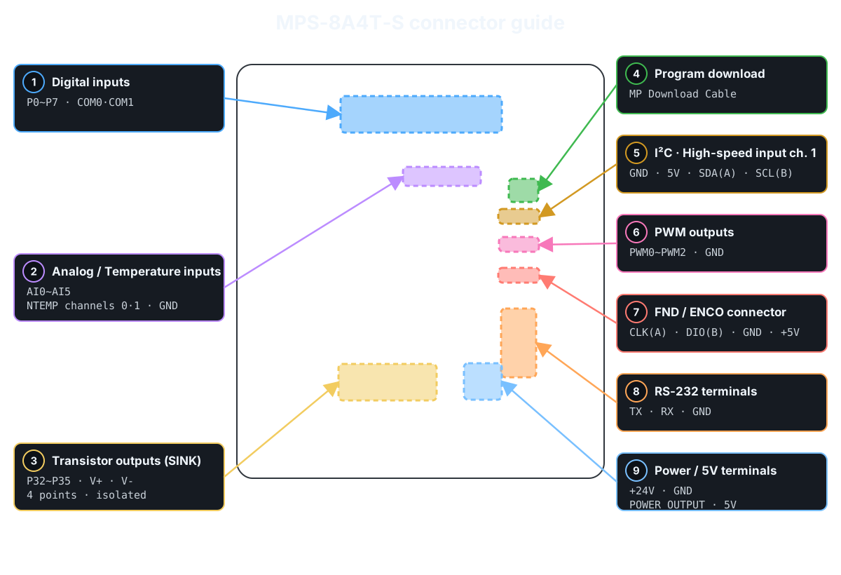
Product Specifications
| Category | Quantity | Terminal / Item | Specifications |
|---|---|---|---|
| Programming method | - | - | MP STUDIO MP STUDIO2 (Ladder logic program) |
| Power | - | Supply voltage | DC 12~24V (0.5A or more when using DC 24V) |
| Digital inputs | 8 points (Solid-state, isolated) | P0~P7 | DC 0~40V; HIGH detection at DC 5V or higher COM0: P0~P3, COM1: P4~P7 NPN/PNP input support |
| Transistor outputs | 4 points (Solid-state, isolated) | P32~P35 | SINK outputs Max. 1A/1 points Connect DC 5~30V to V+ and GND to V- |
| Analog inputs | 6 points (Non-isolated) | AI0~AI5 | AI0·AI1: DC 0~5V or 1~5V AI2·AI3: 0~20mA or 4~20mA AI4·AI5: DC 0~10V |
| Temperature sensor inputs | 2 points (Non-isolated) | NTEMP channels 0·1 | NTC 3950K, 10kΩ(25℃) -40~120℃ |
| High-Speed Counter / Encoder | 2 channels (Non-isolated) | CLK(A)·DIO(B) SDA(A)·SCL(B) | Max. 50kHz Channel 1 is shared with I²C |
| Pulse outputs | 3 points (Non-isolated) | PWM0~PWM2 | DC 5V, Max. 30mA Shares 1 timer |
| Communication Channels | 1 channel (Non-isolated) | I²C | I²C Master, 1:N |
| RS-232 | Modbus RTU Slave LS Industrial Systems Cnet(XGK) Slave IBUS Master·Slave |
||
| Memory | - | Flash | 128KB (32KB used by system) |
| Data Memory | 8KB (1KB used by system) |
Digital inputs
See the one-channel digital-input check before wiring for the first time. →
| Contact | COM | Input type | Connector / Wiring example |
|---|---|---|---|
| P0~P3 | COM0 | NPN/PNP inputs |  |
| P4~P7 | COM1 | NPN/PNP inputs |
Transistor outputs
See the one-channel SINK transistor-output check before wiring for the first time. →
| Contact | Output type | Maximum current | Connector / Wiring example |
|---|---|---|---|
| P32~P35 | SINK: outputs GND connected to V- when ON | 1A/1 points |  |
Connect an external load power supply to the output terminals V+ and V-.
Analog / Temperature inputs
| channel | Input range | Function block | Connector / Wiring example |
|---|---|---|---|
| AI0, AI1 | DC 0~5V or 1~5V | ADC or ADC2 |  |
| AI2, AI3 | 0~20mA or 4~20mA | ADC or ADC2 |
|
| AI4, AI5 | DC 0~10V | ADC |
|
| NTEMP channels 0·1 | NTC 10kΩ, 3950K | NTEMP |
PWM and High-Speed Inputs
| Function | Contacts / Channels | Points | Connector / Wiring example |
|---|---|---|---|
| PWM outputs | PWM0~PWM2 | 3 points |  |
| High-speed counter / Encoder channel 0 | CLK(A), DIO(B) | 1 channel |  |
| I²C · High-speed input ch. 1 | SDA(A), SCL(B) | 1 channel |  |
| FND / ENCO / High-speed input channel 0 | CLK(A), DIO(B) | 1 channel | |
PWM0~PWM2 share one timer; set the same frequency and WIDTH.
Communication and Upload
| Function | Terminals / Cables | Usage | Connector / Wiring example |
|---|---|---|---|
| Program download | MP Download Cable | MP STUDIO download / monitoring |  |
| RS-232 | TX, RX, GND | Modbus RTU Slave, LS Industrial Systems Cnet(XGK) Slave, IBUS Master·Slave | |
| I²C | GND, 5V, SDA, SCL | I²C Master | |
| Power / 5V terminals | +24V, GND / POWER OUTPUT | DC 12~24V input / DC 5V output up to 0.5A |
Basic I/O example
0000 [ P0:Run button ]────────────────( P32:Transistor output )