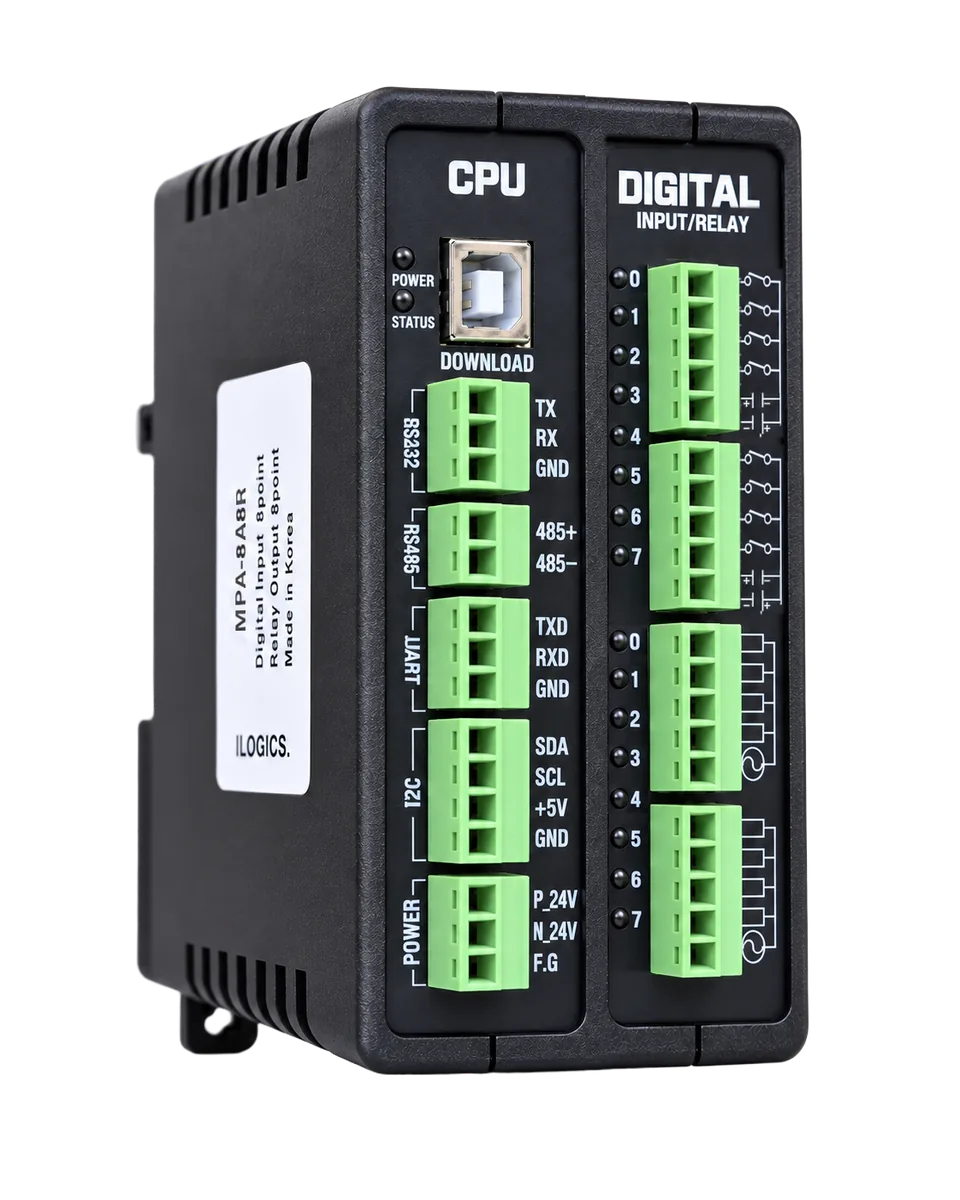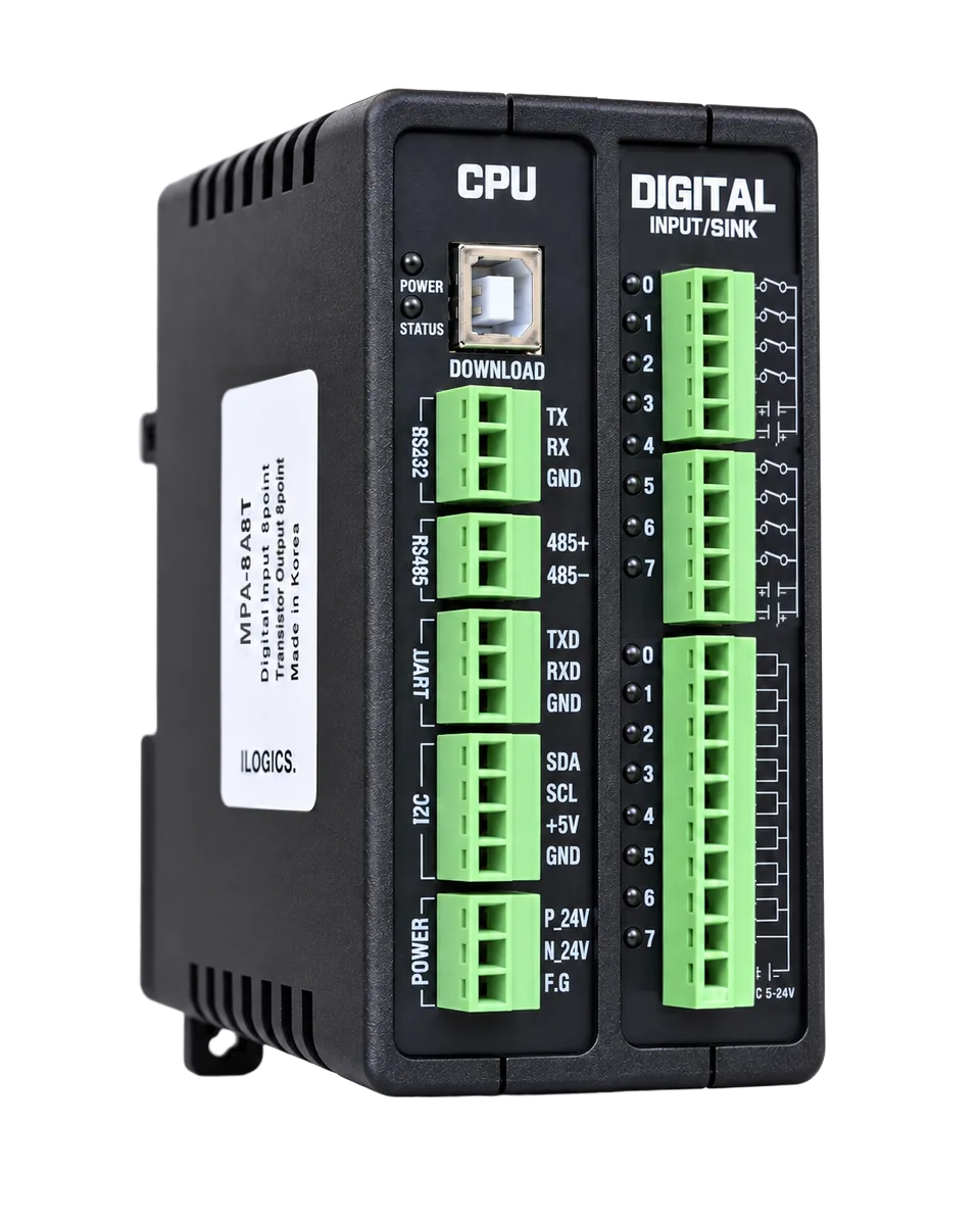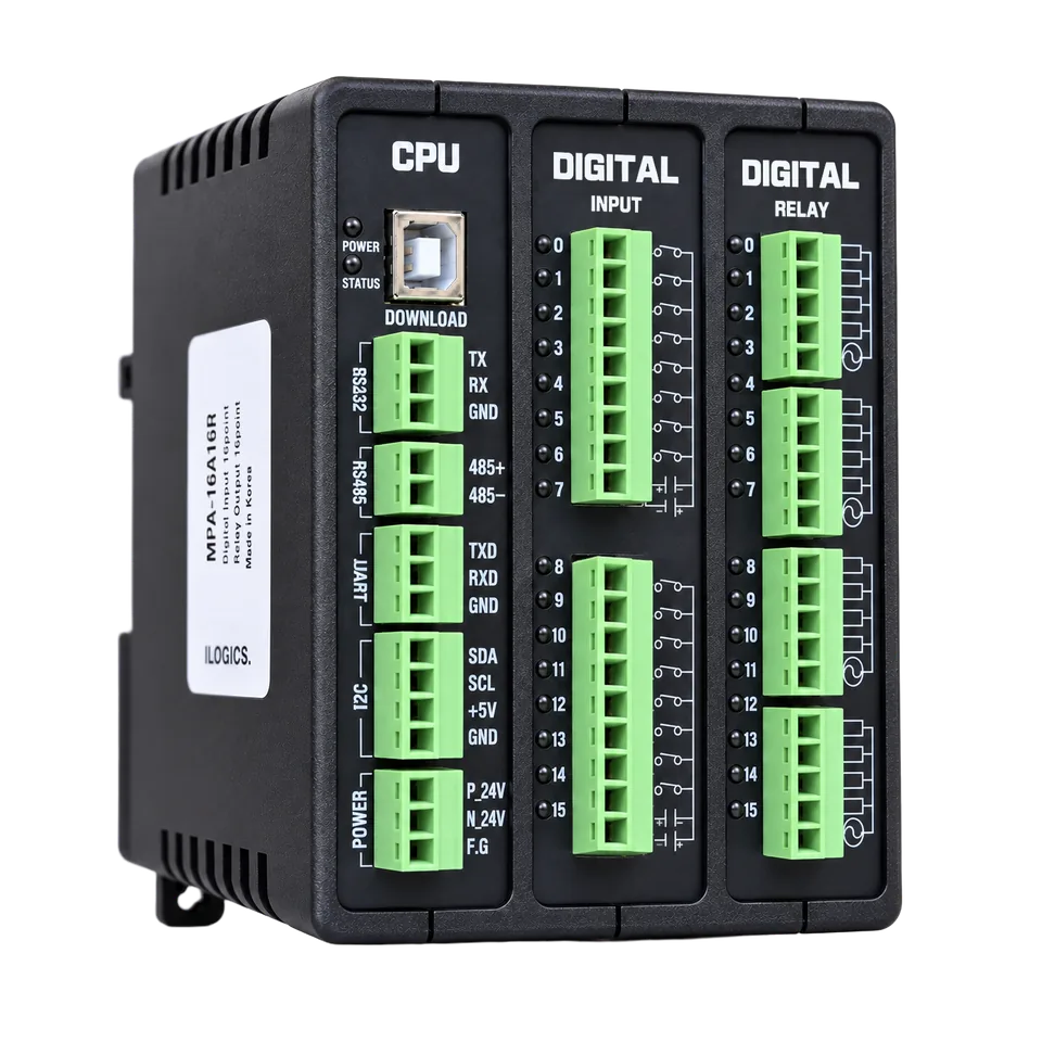
MPA Series
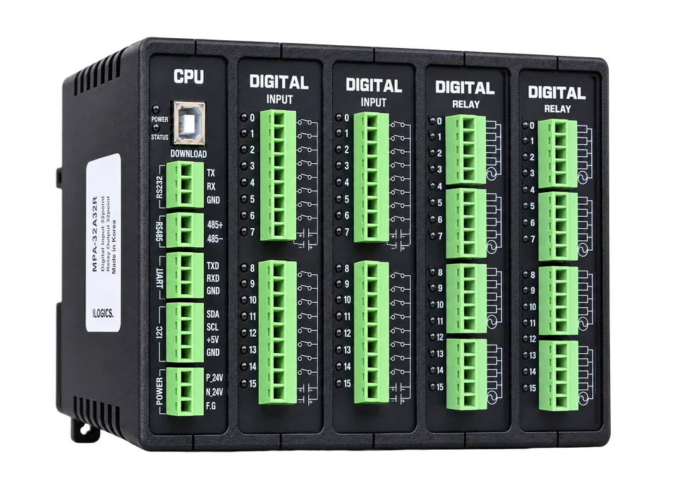
MPA-32A32R
MPA-32A32R PLC - 32 Inputs, 32 Relay Outputs
MPA-32A32R is an industrial PLC programmed in ladder logic with MP STUDIO 2, with 32 isolated digital inputs and 32 relay outputs.


EMS or international air parcel — choose at checkout; rates depend on destination and weight
Shipping weight 1.05 kg (per unit)
Ships the next business day (regardless of order time)
Large orders may take 1 extra day to dispatch
You can cancel before dispatch, and you can request a return or exchange within 7 days of receiving the item.
Products ordered with the “Expansion module” option are modified to your order before shipping, so they cannot be returned or exchanged for a change of mind.
Specifications
/ SPEC| Power input | DC 12V – 24V |
|---|---|
| Digital inputs | 32 |
| Relay outputs | 32 |
| High-speed pulse inputs | 2 |
| Encoder inputs | 2 |
| RS-232 | 1ch |
| RS-485 | 1ch |
| UART | 1ch |
| I²C | 1ch |
| Modbus RTU | Yes |
| LS Cnet | Yes |
Key features
/ FEATURES- Ladder programming with MP STUDIO 2
- DC 12–24V power input
- 32 optocoupler-isolated digital inputs · NPN/PNP compatible, input signal DC 0–80V (HIGH at DC 5V or more)
- 32 relay outputs · max. 5A per point
- I/O module options: analog input (X) · PT100Ω temperature input (F) · analog output (Y) · pulse output (K)
- 2 high-speed counter inputs · optocoupler isolated, max. 8kHz
- 2 encoder input channels · optocoupler isolated, max. 8kHz
- Serial communication: RS-232 · RS-485 · UART · I²C
- 35 mm DIN rail mounting
INDUSTRIAL PLC
32 digital inputs. 32 relay outputs.
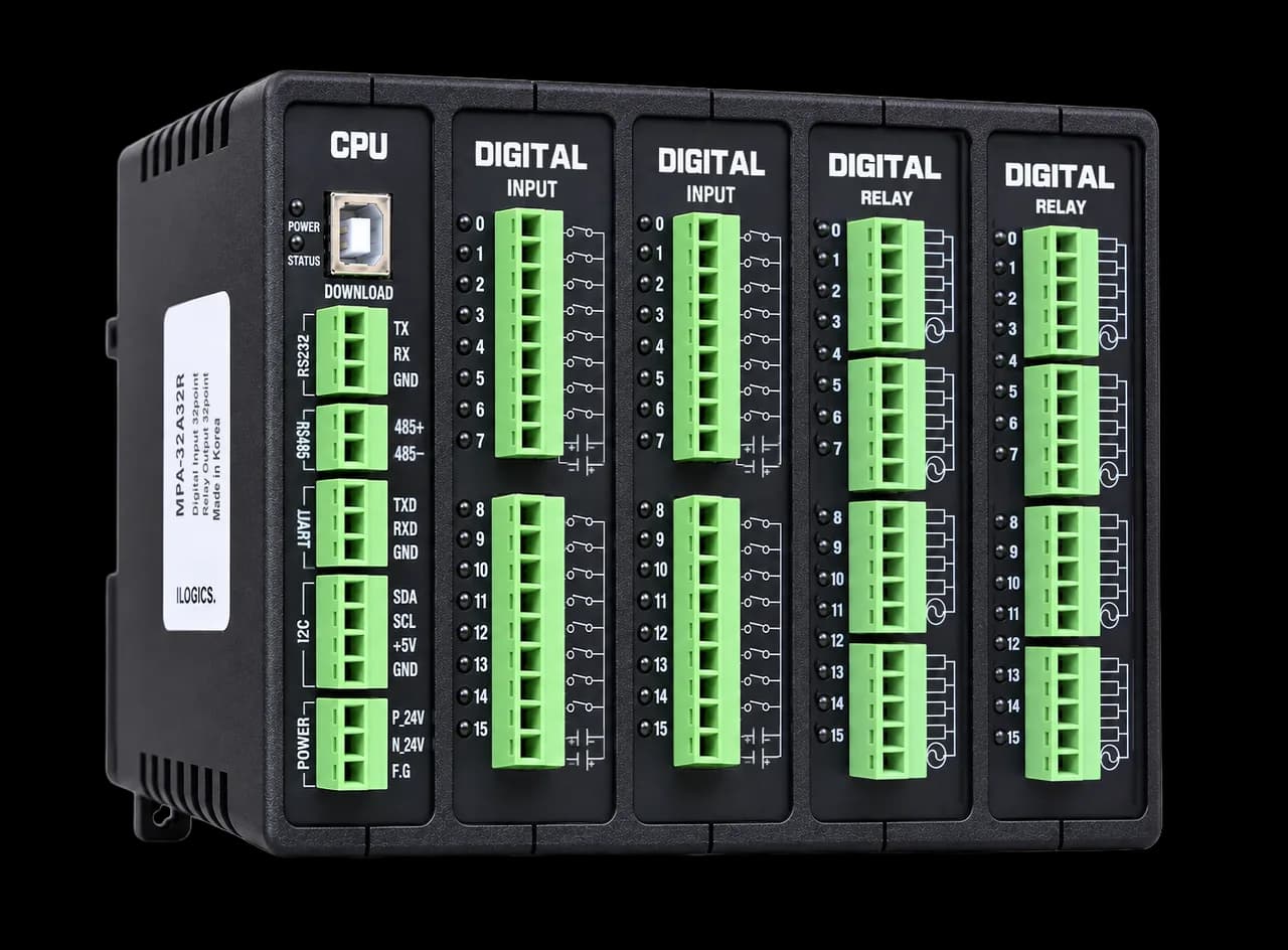
01 Program download (USB-B)
Details Program download (USB-B) · opens in a new tabDOWNLOAD port · download / monitoring, Built-in CP210x
02 STATUS LED
Details STATUS LED · opens in a new tabStatus shown by the @SLED contact
03 RS-232, 1 channel
Details RS-232, 1 channel · opens in a new tabCH1 · TX / RX / GND
04 RS-485, 1 channel
Details RS-485, 1 channel · opens in a new tabCH2 · 485+ / 485−, Modbus RTU · 1:N connection
05 UART, 1 channel
Details UART, 1 channel · opens in a new tabCH3 · TXD / RXD / GND, Also used for the 7-segment display
06 I²C, 1 channel
Details I²C, 1 channel · opens in a new tabSDA / SCL · master · 1:N connection, Character LCD connection
07 DC 12–24V power
Details DC 12–24V power · opens in a new tabP_24V(+) / N_24V(−) / F.G, DC 24V · 0.5A or more recommended
08 32 digital inputs
Details 32 digital inputs · opens in a new tabP0–P31 · COM0 · COM1 on each module, Optocoupler isolated · 8 points / 1 COM × 4 groups, DC 0–80V · P0–P3 shared with the high-speed counter / encoder
09 32 relay outputs
Details 32 relay outputs · opens in a new tabP32–P63 · 4 points / 1 COM × 8 groups, Max. 5A per contact · max. 8A total per COM, Load AC 0–250V or DC 0–30V
- Memory
- Flash 256 KB · Data 8 KB
- Including system area
- Power
- DC 12–24V
- 24V 0.5A or more recommended
- Size / mounting
- Body 136 × 108 mm
- CPU + 2 DIGITAL INPUT modules + 2 DIGITAL RELAY modules · depth 83 mm (body 79 mm) · 35 mm DIN rail mounting
- Development tools
- MP STUDIO 2
- Device: MPA-32A32R(T)
Relay output ratingP32–P63 are dry relay contacts. Each group of 4 points shares one COM. The contact rating is AC 250V or DC 30V, with a maximum of 5A per point and 8A per COM.
Power suppliesThe POWER input takes DC 12–24V, and 24V 0.5A or more is recommended. Relay contacts only open and close the load circuit. They do not supply load power.
Contact numbersTerminals 0–15 on the DIGITAL INPUT modules map in order, from the left module, to contacts P0–P15, P16–P31, and terminals 0–15 on the DIGITAL RELAY modules to P32–P47, P48–P63. The ladder uses these contact names as they are.
Shared terminalsP0–P3 are shared with the high-speed counter and encoder inputs (high-speed counter P0 · P1, encoder P0(A) · P2(B) and P1(A) · P3(B)). When a 7-segment display is connected to the UART terminal, UART (channel 3) communication cannot be used at the same time. A channel set as a Modbus RTU master cannot be used to download programs. See “I/O module options” for the high-speed counter and encoder limits that depend on the option modules.
I/O EXPANSION
I/O module options
Analog input, analog output, PT100Ω temperature input and pulse output modules can be added. The modules you select are assembled with MPA-32A32R and shipped as one product. Base and expansion modules cannot be added or removed by the user.
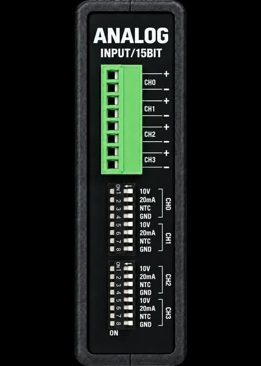
XAnalog input
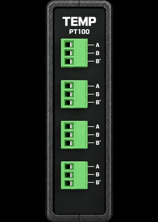
FPT100Ω temperature input
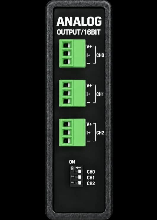
YAnalog output
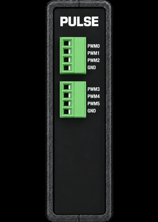
KPulse output
| Module | Type | Per module | Key specs | Max. if used alone |
|---|---|---|---|---|
| ModuleX | TypeAnalog input | Per module4 points | Key specsDC 0–5V · DC 0–10V0–20mA / 4–20mA · NTC temperature sensor | Max. if used aloneUp to 5 (20 points) |
| ModuleF | TypePT100Ω temperature input | Per module4 points | Key specs−200 to +800°C2-wire or 3-wire PT100Ω | Max. if used aloneUp to 5 (20 points) |
| ModuleY | TypeAnalog output | Per module3 points | Key specsDC 0–5V · DC 0–10V0–20mA / 4–20mA · 16-bit | Max. if used aloneUp to 4 (12 points) |
| ModuleK | TypePulse output | Per module6 points | Key specsLOW 0V / HIGH 5V · max. 30mA per channelMax. frequency 1MHz | Max. if used aloneUp to 2 (12 points) |
Limits when choosing modules together
- X + F: a total of up to 5 modules and 20 points.
- Y + K: a total of up to 12 output points. With one K, up to 2 Y modules can be used. With two K modules, Y cannot be used.
- If K2, Y3 or Y4 is installed, or Y and K are installed together, the high-speed counter and encoder inputs cannot be used.
Before you order
- Adding an expansion module means the unit is assembled to your order, so such an order is difficult to exchange or refund.
- A combination that cannot be built is disabled in the option selector, so it cannot be chosen.
| Function needed | Quantity needed | Module chosen | Quantity provided |
|---|---|---|---|
| Function neededAnalog input | Quantity needed6 points | Module chosenX × 2 | Quantity provided8 points · 2 points spare |
| Function neededPT100Ω input | Quantity needed3 points | Module chosenF × 1 | Quantity provided4 points · 1 point spare |
| Function neededAnalog output | Quantity needed3 points | Module chosenY × 1 | Quantity provided3 points |
| Function neededPulse output | Quantity needed6 points | Module chosenK × 1 | Quantity provided6 points |
This example shows how a base product and expansion modules combine. For wiring and program settings, see the manual for that product.
SOFTWARE / DEVELOPMENT ENVIRONMENT
MP STUDIO 2
You can write ladder programs for the MPS and MPA series and check their operation with simulation and monitoring.
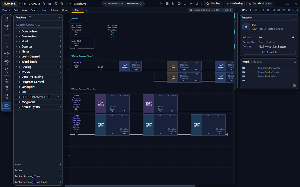
Write ladder logic
Place contacts, coils and wires, and write the control program with function blocks such as timers and counters.
Program check · simulation
Check addresses and memory ranges, and verify ladder operation on the PC by changing inputs, without real equipment.
Download · monitoring
Download the program to the product and check ladder operation and data values in real time.
How to use MP STUDIO 2
For detailed instructions, from model selection to writing ladder logic, downloading and monitoring, see the online manual.
PROGRAM TO PRODUCT
Program download with a USB cable
You can download the program using a USB A to B download cable.
01 COMPUTER
PC for writing programs
USB-A port
02 DOWNLOAD CABLE

Download cable
USB A to B · 1.2 m
03 MPA-32A32R
DOWNLOAD port on the product
USB-B · built-in CP210x
Connect
Connect the PC to the DOWNLOAD port on the product with the download cable. If no COM port appears in Device Manager, install the CP210x driver.
Select model and port
In MP STUDIO 2, you must select the MPA series and MPA-32A32R(T) under Setting > Device, and the matching COM port in Channel under Setting > Communication Port.
Program download
Write the program in MP STUDIO 2 and run the download. After downloading, you can check the input and output states with monitoring.
Check the communication settings and the download method of MP STUDIO 2.
How to download with MP STUDIO 2Port selection · program download opens in a new tabThis product uses a USB-B port. A USB-UART bridge (CP210x) is built into the product, so you download with a USB A to B cable, without an MP download cable.
CP210x USB driverCP210x_Windows_Drivers.zip opens in a new tabCONNECT YOUR DISPLAY
Display connection
You can check control status on an HMI, a character LCD or a 7-segment display.
01 / HMI
HMI
An HMI can be connected over RS-232 or RS-485.
Supported protocols
- Modbus RTU Slave
- Cubloc Modbus RTU Slave
- LS Cnet (XGK/LINK) Slave
Check the HMI's protocol, baud rate, station number and wiring.
Serial communication terminal guideRS-232 · RS-485 · UART terminals · supported protocols opens in a new tabMP STUDIO 2 Communication Port settingsCOM port · baud rate settings opens in a new tabPRODUCT
RS-232 · CH1
DEVICE
HMI RS-232
- TXRX
- RXTX
- GNDSG
PRODUCT
RS-485 · CH2
DEVICE
HMI RS-485
- 485+485+
- 485-485-
02 / CHARACTER LCD
Character LCD
You can connect a 1602 or 2004 character LCD with a PCF8574 I²C adapter module to the I2C terminal.
PRODUCT
I2C
DEVICE
I²C module
- SCLSCL
- SDASDA
- +5VVCC
- GNDGND
Connect +5V and GND at the same I2C terminal. Set the address and the row and column size to match your module.
03 / 7-SEGMENT LED
7-segment display
A TM1637 7-segment display can be connected to the UART terminal.
PRODUCT
UART · I2C
DEVICE
7-segment module
- RXDCLK
- TXDDIO
- +5V5V
- GNDGND
RXD on the UART terminal is used as CLK and TXD as DIO, and 1 display can be connected. While a 7-segment display is connected, UART (channel 3) communication cannot be used. Connect +5V and GND at the I2C terminal. Check whether you need the decimal-point type or the clock type.
This is a functional connection diagram by terminal name, not the physical pin order of the connector. Displays and connection cables are not included.
PACKAGE CONTENTS
Package contents
See what is included and what is optional.
Not includedENGINEERING DETAILS
Details by function
See contacts, wiring diagrams and pre-use checks for each function.
Digital inputClose
Digital input
32 isolated digital input channels
32 digital input channels read external switches and sensors straight from the terminal block. In the ladder program they are the contacts P0–P31. The inputs are split 16 + 16 across 2 I/O modules.
P0–P31 inputs
32 isolated digital input points in total
COM0 / COM1 commons (2 per module)
Module 0 COM0 = P0–P7 · COM1 = P8–P15 | Module 1 COM0 = P16–P23 · COM1 = P24–P31 (8 points per COM)
DC 0–80 V input
DC 5 V and above reads as HIGH · optocoupler isolated
NPN / PNP sensors
Either sensor wiring convention is read as-is
Input channel layout
* Example wiring for external switches or sensors — applying DC 5 V–24 V at the terminal turns that contact memory ON
Optocoupler isolation
The digital inputs run through an optocoupler stage, so the field wiring stays electrically separate from the control circuit.
Example ladder — reading an input
        P0                                  P32
0000  --| |---------------------------------( )--

  P0 = push button (digital input), P32 = the load on the first relay output.
  P0 ON  -> P32 ON        P0 OFF -> P32 OFF
  Module 0 returns P0~P7 on COM0 and P8~P15 on COM1 - eight points per common.
  Module 1 carries P16~P31 the same way, on a COM0 and COM1 of its own.
Relay outputClose
Relay output
32 isolated relay contact outputs
32 volt-free relay contacts switch DC or AC loads directly. In the ladder program, turning the contacts P32–P63 ON closes the matching relay onto its COM. The outputs are split 16 + 16 across relay modules 2 and 3.
P32–P63 outputs
32 isolated relay points in total
COM0 / COM1 / COM2 / COM3 commons (4 per module)
Module 2 COM0 = P32–P35 · COM1 = P36–P39 · COM2 = P40–P43 · COM3 = P44–P47 | Module 3 COM0 = P48–P51 · COM1 = P52–P55 · COM2 = P56–P59 · COM3 = P60–P63 (4 points per COM)
DC 0–30 V / AC 0–250 V
Volt-free contacts, so DC and AC loads both wire straight to the terminal
5A / 1POINT · 8A / 1COM
Maximum switching current, per point and per COM
Relay output layout
* Each block of 4 points shares one COM — the load supply arrives on that COM, and each relay module carries 4 of them
Relay contact structure
The MCU drives the relay coil through an optocoupler and the contact itself is volt-free, so the load circuit shares nothing electrically with the controller.
Example ladder — driving a relay output
        P1                                  P33
0000  --| |---------------------------------(S)--

        P2                                  P33
0001  --| |---------------------------------(R)--

  P1 = start button, P2 = stop button, P33 = the load on the second relay output.
  P1 ON latches P33 on (it stays on when P1 is released); P2 ON clears it.
  P32~P35 share module 2's COM0 - four of that bay's sixteen outputs take their
  load supply from it. Module 3 (P48~P63) carries its own COM0~COM3.
High-speed counter · encoderClose
High-speed counter · encoder
2 isolated high-speed counter / encoder channels
Pulses that arrive faster than one program scan are counted in hardware. Counter channels 0 and 1 are the digital input contacts P0 · P1 themselves, so no extra terminal is needed — and the same contacts read a two-phase encoder.
P0 · P1 counters
Max 8kHz, counting 0 ~ 4,294,967,295 — read with the HCNT function block
Encoder pairs
Channel 0 P0(A)·P2(B) · Channel 1 P1(A)·P3(B) — Max 8kHz, -2,147,483,648 ~ 2,147,483,647
Shared with the inputs
There are no counter or encoder terminals of their own — the contacts they use are P0 · P1.
Counter and encoder wiring
* The counter and the encoder are wired to the same contacts.
Before you wire it
- Fitting expansion modules K2 · Y3 · Y4 · YK · Y2K makes channels 0 and 1 unavailable.
Channels and contacts
| Channel | Contacts | Characteristics |
|---|---|---|
| Channel 0 | ContactsP0 · encoder P0(A)·P2(B) | CharacteristicsIsolated · Max 8 kHz |
| Channel 1 | ContactsP1 · encoder P1(A)·P3(B) | CharacteristicsIsolated · Max 8 kHz |
Counter range 0 ~ 4,294,967,295 · encoder range -2,147,483,648 ~ 2,147,483,647. Function blocks published by this manual: HCNT · ENCODER.
HCNT — counting
        @ON                       HCNT
0000  --| |-----------------------[ CHANNEL:0 | OUT:D100 ]--

  @ON is always on, so the counter free-runs and D100 always holds the count.
  CHANNEL selects the counter input port (0 or 1); OUT is the memory the count
  is stored in.
ENCODER — encoder value
        @ON                       ENCODER
0000  --| |-----------------------[ CHANNEL:0 | OUT:DD0 ]--

  Channel 0's encoder value is kept in the double-word memory DD0.
Communication ports (RS-232 · RS-485 · UART · I²C · program download)Close
Communication
three serial channels plus I²C
RS-232 · RS-485 · UART sit on the CPU module's terminal block as three independent channels, each with its own MP STUDIO channel number (Channel 1 · Channel 2 · Channel 3), and an I²C master port sits beside them. A user-defined protocol can be written in NORMAL MODE with the PUT, GET, PUTLEN, GETLEN function blocks.
RS-485 multidrop
485+ and 485- — two wires carry several devices on one pair
Modbus RTU
Master or slave on each channel. Several channels can run as masters at once.
I²C · 1:N
SDA · SCL · +5V · GND — master mode only, for a character LCD and other I²C devices
Ethernet via M-ETHER
M-ETHER converts Ethernet to RS-232 / RS-485, and Download Mode makes remote download and debugging possible
RS-485 link
* Several devices share one 485+ / 485- pair. The channel number the ladder uses is Channel 2.
Terminal blocks
* All four groups are screw poles on the CPU module, silkscreened I2C · RS232 · RS485 · UART. Note that RS-232 is marked TX / RX while UART is marked TXD / RXD.
Channels and terminals
| Channel | Terminals | Silkscreen |
|---|---|---|
| RS-232 · Channel 1 | TerminalsTX · RX · GND | SilkscreenRS232 |
| RS-485 · Channel 2 | Terminals485+ · 485- | SilkscreenRS485 |
| UART · Channel 3 | TerminalsTXD · RXD · GND | SilkscreenUART |
| I²C · master | TerminalsSDA · SCL · +5V · GND | SilkscreenI2C |
| NORMAL MODE | TerminalsPUT, GET, PUTLEN, GETLEN | SilkscreenUser-defined protocol |
Supported protocols: Modbus RTU Master/Slave · Cubloc Modbus RTU Slave · LS ELECTRIC Cnet(XGK/LINK) Slave · IBUS. Channel numbers and port settings are changed in MP STUDIO's communication port settings.
Before you wire it
- Several channels can run as a Modbus RTU master at once. A channel set as a master cannot be used to download a program.
- Download Mode makes program download and debugging possible over Channel 1 · Channel 2 · Channel 3 as well.
Power · Data retentionClose
Power · Data retention Power · Backup
DC 12V ~ 24V in, 5 V out — and your data survives the blackout
The controller takes DC 12V ~ 24V and an on-board regulator converts it to 5 V for the internal circuit. Size the supply for at least 24V 0.5A.
DC 12V ~ 24V
Size the supply for 24V 0.5A or more
5 V internal
On-board regulator conversion
+5 V out
From the I²C terminal block — limit not published
Supercapacitor hold-up
Holds the +5 V rail up through a power cut
Before wiring the supply
- An EEPROM section written about 100,000 times can fail, and a failed section reads back a random value after a power cut. For values that change constantly, use the supercapacitor method below.
- USB power is for development and bench testing. With every output on, the board draws roughly 5 V 1 A — more than a PC port is meant to give — so the manual asks you to use a powered USB hub, or the external supply, once outputs are wired.
- Do not exceed the stated input voltage range.
- Do not reverse the supply polarity or mis-wire the input.
Where the power goes
* Either source runs the controller: the external supply through the regulator, or the download port's 5 V directly. The supercapacitor sits on the same 5 V node and keeps it alive when both go away.
Power and data retention
| Input voltage | DC 12V ~ 24V |
|---|---|
| SMPS requirement | 24V 0.5A or more |
| Internal conversion | On-board regulator to 5 V |
| +5 V output | From the +5 V pole of the I²C terminal block — this model's manual states no current limit |
| USB-powered operation | Runs on the PC's 5 V through the download port |
| Non-volatile memory | EEPROM, about 100,000 writes per section |
| Hold-up on a power cut | Supercapacitor on the +5 V pole |
| Blackouts retained | More than 100,000, writing only when the mains drops |
Size the supply for 24V 0.5A or more, plus whatever the +5 V pole is feeding.
Keeping data through a blackout
Which method you want depends on how often the value changes. The first is a setting; the second needs one part and a few rungs.
EEPROM retentive area — values that change occasionally
Mark a retentive area under Settings → Data Memory in MP STUDIO and the runtime copies that memory into non-volatile EEPROM every time its value changes — no code to write. Because a section survives only about 100,000 writes, it belongs to setpoints, calibration data and machine configuration rather than to anything the scan updates.
Supercapacitor — values that change constantly
Fit a supercapacitor to the +5 V pole and the internal 5 V stays up for a moment after the main supply is cut. Wire the main supply into a digital input as well, add a rung that moves the live value into the retentive memory as soon as that input goes off, and a second rung that moves it back once on restart. The EEPROM is then written only at the instant of a blackout, so it survives more than 100,000 of them.
FIT YOUR PANEL
Dimensions
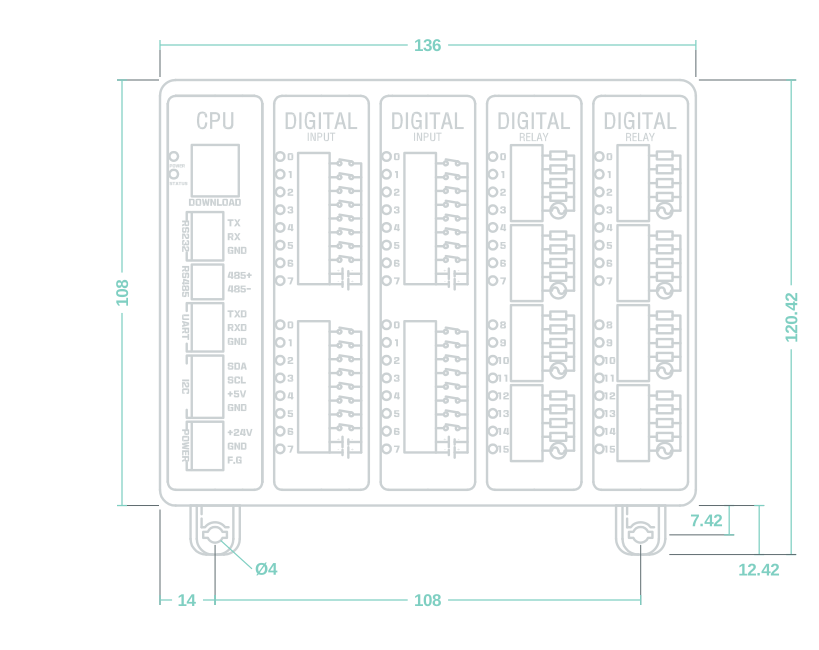
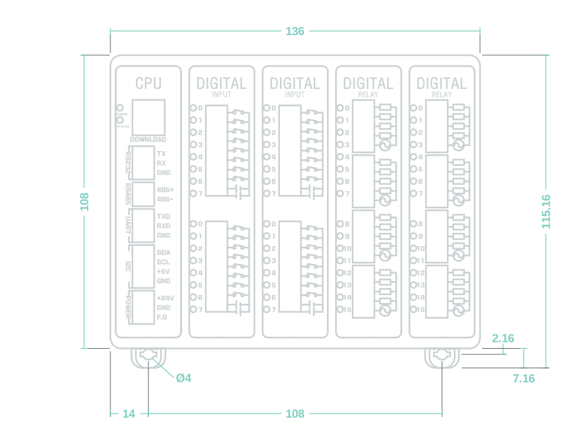
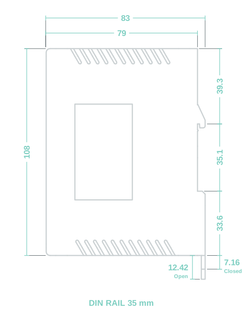
Unit: mm
Installation dimensions
| Body | 136 × 108 mm |
|---|---|
| Clip open | Width 136 × height with clip 120.42 mm |
| Clip closed | Width 136 × height with clip 115.16 mm |
Before installation
- This product must not be installed where it is exposed to rain, frost or condensation.
- This product must not be installed where flammable or explosive gases are present.
- When used in equipment that can seriously affect human life or property (nuclear, medical, vehicle, aviation, disaster prevention, etc.), redundant safety devices must be installed.
READY TO START
Development resources
For detailed wiring and usage, see the MPA-32A32R online manual.
Back to the top of the details
FAQ
Can I use an off-the-shelf USB cable to download?▾
Yes. This product has a built-in USB-UART bridge (CP210x), so you can download the program with a standard USB A to B cable. Connect it to the DOWNLOAD port on the product. The download cable can be added from the add-on products.
Can I program it with the Arduino IDE?▾
No. The MPA series is programmed in ladder logic with MP STUDIO 2. To develop with the Arduino IDE, please use the MPAINO series.
How safe is the product?▾
We have been developing and selling PLCs and industrial Arduinos since 2015. Products we sold 10 years ago are still working without problems.