
MPAINO Series
MPAINO-8A8T
MPAINO-8A8T Industrial Arduino Controller
MPAINO-8A8T is an ATmega2560-based industrial Arduino-compatible PLC controller with 8 isolated digital inputs and 8 transistor (sink) outputs. Onboard RS-232, RS-485, UART, I²C with Modbus RTU, programmable in the Arduino IDE. DIN-rail mountable for automation, testing, HMI integration and embedded control.
International shipping (EMS) — calculated at checkout by destination & weight
Shipping weight 350 g (per unit)
Ships the next business day (regardless of order time)
Large orders may take 1 extra day to dispatch
Cancel before dispatch · request a return/exchange after delivery
Key features
/ FEATURES- ATmega2560 core, programmable in the Arduino IDE and MPINO STUDIO2
- 8 opto-isolated digital inputs (NPN/PNP, up to 40 V tolerant)
- 8 transistor (sink) outputs for fast DC switching
- Industrial communication: RS-485, RS-232, UART, I²C · Modbus RTU
- DIN-rail 35 mm mountable, isolated field I/O for the factory floor
Specifications
/ SPEC| MCU | ATmega2560 |
|---|---|
| Power input | DC 12V – 24V |
| Digital inputs | 8 |
| Transistor outputs | 8 |
| RS-232 | 1ch |
| RS-485 | 1ch |
| UART | 1ch |
| I²C | 1ch |
| Modbus RTU | Yes |
| LS Cnet | Yes |
| Mitsubishi MC | Yes |
| Arduino IDE compatible | Yes |
Software
Arduino IDE / MPINO Studio 2
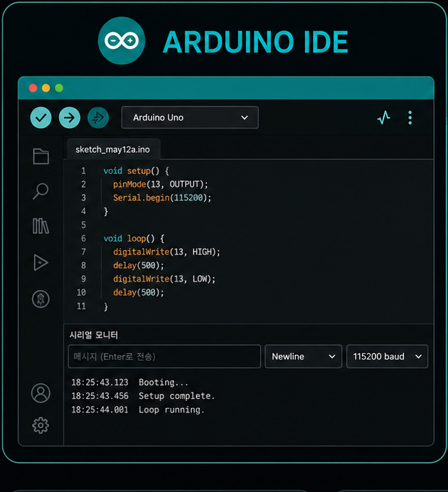
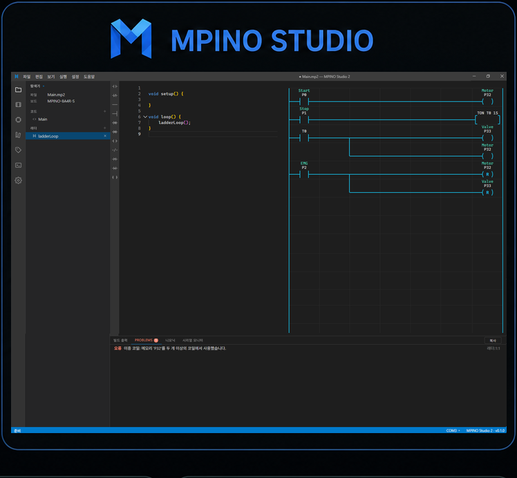

Arduino IDE compatible
Works with the Arduino toolchain you already use

MPINO STUDIO2 included
Arduino code and ladder logic in one tool

Arduino + ladder logic
Build control logic faster with familiar ladder rungs
Setting up the toolchain
Installing the ARDUINO SDK adds this product's board definition to the Arduino IDE and makes the functions that earn their keep in industrial work available as built-in commands. There is no library to add — the Arduino IDE offers them with autocompletion as you type.
Built-in commands the SDK unlocks
- PLC timers · callback timersIton · Itof · Itpl · Itmr · ItimerSet
- CountersIctu · Ictd · Ictud · IgetCount
- Scaling · PID controlIscale · Iscalef · IpidSet · IpidRun
- First-in and last-in buffersFIFO · FILO
- Input debounce · edge detectionIbounce · IdigitalRead · Iup · Idown · Ialt
- Debug · watchdogdebug · debugln · WDT_ENABLE · WDT
- Modbus RTU · LS Cnet · Mitsubishi MCImodbusRTU · ICnet · IMcProtocol
Using the Arduino IDE requires the ARDUINO SDK (the ILOGICS board package) to be installed. MPINO STUDIO2 can be used without installing it.
This board can also be used without the ARDUINO SDK by selecting the MEGA2560 board in the Arduino IDE. In that case the ILOGICS built-in commands are not available.
Digital input
8 isolated digital input channels
Eight photocoupler-isolated input channels read external switches and sensors, in modules of eight wired four points per common.
D0–D7 inputs
Eight digital input points in total
4P / 1COM
Four points per common
Optocoupler isolation
Control circuit protected from field noise
NPN / PNP sensors
Selectable per common · DC 0–40V, HIGH from DC 5V
Input channel layout
* Example wiring for the input module (8 points, 4P / 1COM). The terminal numbers are the ones a sketch passes — without the D — to digitalRead() / digitalWrite() once the ARDUINO SDK is installed.
Optocoupler isolation
Each input is isolated by a bidirectional photocoupler, so either an NPN or a PNP sensor can drive it and the choice is made per common. Inputs accept DC 0–40V and recognise HIGH from DC 5V upwards.
Example sketch — reading an input
void setup() {
  pinMode(0, INPUT);     // terminal D0 - the first digital input
  pinMode(64, OUTPUT);   // terminal D64 - the first digital output
}

void loop() {
  digitalWrite(64, digitalRead(0));
}
Transistor output
8 isolated sinking transistor outputs
Eight sinking outputs. Driving an output HIGH connects its terminal to the GND wired to N24 (V−), so the load hangs between P24 (V+) and the output terminal.
D64–D71 outputs
Eight sinking transistor points
P24 / N24 supply
DC 5–24V on P24 (V+), its GND on N24 (V−)
1A / point · 8A / COM
8P / 1COM · load voltage up to DC 100V
Isolated output
Output stage separated from the control circuit
Output channel layout
* Example wiring for the output module (8 points, 8P / 1COM). The terminal numbers are the ones a sketch passes — without the D — to digitalRead() / digitalWrite() once the ARDUINO SDK is installed.
Sinking output structure
The outputs sink: when a point turns on, its terminal is connected to the GND fed into N24 (V−). Wire the load between P24 (V+) and the output terminal. Each point carries up to 1A and each common up to 8A, at load voltages up to DC 100V. The output stage is isolated from the control circuit.
High-speed pulse outputPulse output · K / K2
Six or twelve points, added as an expansion module
Pulse output is not brought out on the controller's own terminals — it arrives with the K module (6 points) or the K2 module (12 points), ordered together with the board. In the sketch the points are logical channels numbered from 0: FDPWM(channel, hertz, duty) sets a frequency and a duty cycle, PWM(channel, duty) changes the duty alone, and the SDK maps the channel onto the module's own circuit. Analog output (Y) and pulse output (K) draw on the same 12-point budget, so the combination decides what is left.
K = 6 points · K2 = 12 points
Chosen at order time, on this product's option list
Logical channels from 0
FDPWM(ch, Hz, duty %) · PWM(ch, duty)
12 points shared with analog output
Y and K spend one budget between them
K2 cannot take a Y module
The SDK refuses to compile the pair
Non-isolated · LOW 0 V / HIGH 5 V
Up to 30 mA per point, behind a 100 Ω series resistor, with a TVS fitted
Example sketch — frequency and duty
void setup() {
  // Channel 0 of the K2 module's 12 channels, at 1 kHz and 50% duty
  FDPWM(0, 1000, 50.0);
}

void loop() {
}
Example sketch — duty only
void setup() {
  // 8-bit duty, 0-255. Pass true as the third argument for 16-bit, 0-65535
  PWM(0, 128);
}

void loop() {
  PWM(0, 200);   // change the duty only
  delay(1000);
  PWM(0, 60);
  delay(1000);
}
What each combination leaves you
| Combination | Pulse output | Interrupts 0–1 |
|---|---|---|
| K on its own | 6 points | Unaffected |
| K2 | 12 points · 10 with interrupts in use | Terminals move onto the module — the count is unchanged |
| Y + K | 6 points (9 with the Y's 3) | Cannot be used |
| Y2 + K | 6 points (12 with the Y2's 6 — the ceiling) | Cannot be used |
The channel numbers are the SDK's logical pulse channels, a separate numbering from the digital I/O terminals. Analog output and pulse output share one 12-point budget, which is why Y2 + K reaches the ceiling exactly. The output stage is the same circuit as on the MPINO controllers, so the electrical figures are theirs. The usable frequency range is not published for either family and is deliberately not stated here.
Before you order
- There is no pulse output without the module: the controller's own terminals do not carry it.
- K2 cannot be fitted together with an analog output (Y) module.
- Fitted alongside analog output, K goes with Y or Y2 only — not with Y3 or Y4.
- Analog output and pulse output together cannot exceed 12 points.
- Fitting K2 moves interrupts 0 and 1 onto the pulse output module's own terminals. The interrupt count does not change; using them as interrupts leaves 10 of the module's 12 pulse output points.
- Fitting an analog output (Y) and a pulse output (K) module together makes interrupts 0 and 1 unusable.
- K on its own leaves the interrupts alone.
- The outputs are non-isolated 5 V logic. Do not draw more than 30 mA from a point — drive a larger load through a relay output, a transistor output or an external driver.
External interruptInterrupt · Encoder
Four external interrupts — two isolated, two fast
Interrupts 0 and 1 are digital input terminals D0 and D1, on the same isolated circuit as the rest of the inputs, so a DC 24 V field signal goes straight in, at up to 8 kHz. Interrupts 2 and 3 are the SDA and SCL poles of the I²C terminal: not isolated, but they carry built-in 4.7 kΩ pull-ups and take at least 50 kHz. Register an ISR with attachInterrupt(digitalPinToInterrupt(n)) and the sketch catches every edge without polling. Wire a two-phase encoder across a pair of them and the same inputs read its rotation and direction.
4 interrupt inputs
0 · 1 · 2 (SDA) · 3 (SCL)
2 isolated · up to 8 kHz
0 · 1, on the digital inputs' own circuit
2 non-isolated · 50 kHz and above
2 · 3, on the I²C terminal's SDA · SCL
4.7 kΩ pull-ups
Built in on both non-isolated inputs
Rotary encoder
Across SDA · SCL, or across inputs 0 · 1
Interrupt number mapping
| Interrupt | Terminal | Type · input frequency |
|---|---|---|
| 0 | Digital input D0 | Isolated · input module COM0 · up to 8 kHz |
| 1 | Digital input D1 | Isolated · input module COM0 · up to 8 kHz |
| 2 | SDA | Non-isolated · 4.7 kΩ pull-up · 50 kHz or more |
| 3 | SCL | Non-isolated · 4.7 kΩ pull-up · 50 kHz or more |
The numbers in this table are the logical interrupt numbers you pass to attachInterrupt(digitalPinToInterrupt(n)) once the ARDUINO SDK is installed — a separate numbering from the digital input numbers. Interrupts 0 and 1 run on the digital-input circuit, so they take DC 0–40 V with HIGH recognised from DC 5 V, and they share their input module's COM0. SDA and SCL are the MCU's own I²C pins and are DC 0–5 V only. The detection modes are LOW, CHANGE, RISING and FALLING. What frequency a sketch actually keeps up with depends on the length of the ISR and the load of the whole program, so no fixed figure is guaranteed.
Interrupt input wiring
* On the left, the isolated interrupt is the digital-input circuit itself: DC 5–24 V goes to input terminal D0 and its ground to COM0 on the same module, and the opposite polarity is wired just as well (NPN / PNP). On the right, SDA and SCL are poles of the I²C terminal with 4.7 kΩ pull-ups already fitted, so only a DC 5 V signal may be connected there.
Before you wire it
- Fitting the K2 pulse output module moves interrupts 0 and 1 onto the pulse output module's own terminals. The interrupt count does not change; using them as interrupts leaves 10 of the module's 12 pulse output points.
- Fitting Y3 or Y4 analog output modules, or an analog output (Y) and a pulse output (K) module together, makes interrupts 0 and 1 unusable.
- Fitting an add-on module rewires the digital input terminals internally (D2–D9 → D22–D29).
- If SDA and SCL are used as interrupts 2 and 3, I²C communication cannot be used at the same time.
- The non-isolated inputs take DC 0–5 V only. Put a DC 24 V signal through the isolated interrupts 0 · 1 instead.
- These four are the only external interrupts this board has.
- Do as little as possible inside the ISR — no Serial output, no delay(), nothing that takes time.
Example sketch — external interrupt
void setup() {
  Serial.begin(9600);
  // interrupt 0 = digital input D0 - a rising edge calls _INT0()
  attachInterrupt(digitalPinToInterrupt(0), _INT0, RISING);
}

void loop() {
}

void _INT0() {
  Serial.println("ok");
}
Example sketch — rotary encoder
volatile long encoderValue = 0;

void setup() {
  Serial.begin(115200);
  // interrupt 0 = digital input D0, phase B on digital input D1
  attachInterrupt(digitalPinToInterrupt(0), updateEncoder, FALLING);
}

void loop() {
  Serial.print("Encoder Value: ");
  Serial.println(encoderValue);
  delay(500);
}

void updateEncoder() {
  if (digitalRead(1)) { encoderValue++; }
  else                { encoderValue--; }
}CommunicationRS-232 · RS-485 · UART · I²C
Four communication channels on the CPU module
Every communication terminal sits together on the CPU module. RS-232 is Serial1, RS-485 is Serial2 and the TTL UART is Serial3, each on its own screw terminal, and I²C is the Wire library with 4.7 kΩ pull-ups already fitted for 1:N connections. Modbus RTU, the standard on the plant floor, works as either master or slave through the SDK's built-in command set.
RS-485 · 1 channel
Serial2 · 1:N multidrop on the 2-pole 485+ / 485− terminal
RS-232 · 1 channel
Serial1 · point-to-point on the 3-pole TX, RX, GND terminal
UART (TTL) · 1 channel
Serial3 · TXD, RXD, GND terminal · TX = D14, RX = D15
I²C · 1 channel
Wire · 4.7 kΩ pull-ups built in · 4 poles including +5V
Modbus RTU
Master or slave through the SDK's built-in command set
RS-232 · UART · I²C · USB connectors
* The communication terminals run down the left edge of the CPU module, and each one is drawn as its silkscreen reads. The I²C terminal carries +5V and GND alongside the two signals, so an I²C device can take its power from the same connector. The program port is silkscreened DOWNLOAD.
RS-485 link
* The 2-pole screw block on the CPU module, 485+ above 485−. RS-485 is a multidrop bus, so 485+ goes to every node's 485+ and 485− to every node's 485−. This is the channel the plant floor runs Modbus RTU on.
Communication ports
| Port | Pins | Use |
|---|---|---|
| Serial | USB (DOWNLOAD) | Program upload and debug over the download port |
| Serial1 | TX · RX · GND terminal | RS-232 · point-to-point |
| Serial2 | 485+ · 485− terminal | RS-485 · 1:N multidrop |
| Serial3 | TX = D14 · RX = D15 | TTL UART · point-to-point |
| Wire (I²C) | SDA = D20 · SCL = D21 | I²C · 1:N |
All four external ports support Modbus RTU as master or slave. The UART channel is TTL level with no line driver, so it reaches a nearby module rather than running a long cable. The I²C terminal has four poles — SDA, SCL, +5V, GND — with 4.7 kΩ pull-ups already fitted, and takes accessories such as a DS3231 RTC or a 1602 / 2004 character LCD.
Before you wire it
- The +5V pole of the I²C terminal is a regulator OUTPUT and can supply an external device with up to 1 A.
- Using SDA and SCL as external interrupts or as an encoder input means I²C cannot be used at the same time.
- The UART channel is TTL level and is not isolated — do not connect it to an RS-232 or RS-485 line directly. Wiring a 7-segment display to the UART occupies the same channel.
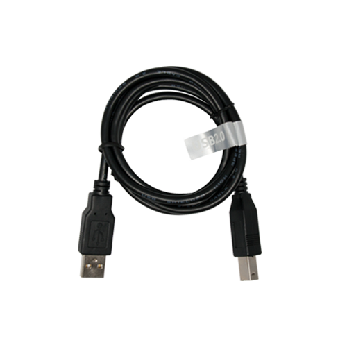
- An ordinary USB cable uploads. Install the Silicon Labs CP210x driver first, then pick the COM port it creates in the Arduino IDE.
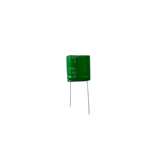
- The board runs on the PC's 5 V through the DOWNLOAD port even with no +24 V applied. A supercapacitor on the I²C terminal's +5V pole holds the internal 5 V up through a power cut — see Power · Data retention below.
Example sketch — serial send and receive
void setup() {
  Serial.begin(9600);    // USB DOWNLOAD port, for monitoring
  Serial1.begin(9600);   // RS-232
  Serial2.begin(9600);   // RS-485
  Serial3.begin(9600);   // UART
}

void loop() {
  Serial2.println("Hello RS485");

  while (Serial2.available()) {
    char c = Serial2.read();
    Serial.write(c);     // echo the reply to the USB monitor
  }
  delay(1000);
}7-segment (FND) connectionFND · TM1637
A four-digit 7-segment display on two signal wires — up to 7 of them
The display module carries a TM1637 driver, so a four-digit readout needs only a clock line and a data line. This board has no dedicated display connector: the two signals go on ordinary screw poles — CLK = TXD · DIO = RXD is the recommended pair — and +5V and GND come off the I2C terminal block, which makes the whole run four wires.
Two wires: CLK and DIO
A TM1637 four-digit module needs no more
Up to 7 displays
Each on its own pair of poles
Powered from the board
+5V · GND on the I2C terminal block · up to 1A
Built-in commands
IsegDecimal and IsegHex print decimals and hex
Displays and their poles
| Display | Terminals | Pins |
|---|---|---|
| Display 1 | CLK = TXD · DIO = RXD | D14 · D15 |
| Displays 2–4 | K module PWM0–PWM5 | Three per module |
| Maximum | Two K modules fitted | Seven in total |
| Supply | +5V · GND | Board output · up to 1A |
The signal poles are the Serial3 UART terminals doing double duty, so a pole driving a display is spent for as long as it does. The +5V pole is an output on this board, which is what lets the display run without a supply of its own. The display module itself is an accessory sold separately.
Recommended connection
* The poles are silkscreened TXD · RXD · +5V · GND; nothing on the board says CLK or DIO, so the role of each wire is printed where it lands. TXD is D14 and RXD is D15. The display comes in a decimal-point form and a time-displaying form, both sold separately.
Driving more than one
* Every display needs its own CLK and DIO pair; +5V and GND are shared by all of them. The pole names below are read left to right off the board, which is why the clock line is not always the left-hand one.
Before you wire it
- A pole used for a display cannot be used as the Serial3 UART at the same time.
- The Iseg commands in the sketch below are built into the ARDUINO SDK — install the SDK and they are available, with no library to add and no #include to write.
- The K pulse-output module is an add-on. In the base configuration one display goes on the UART poles.
- On this board +5V and GND are on the I2C terminal block, not on a separate power block.
- The 7-segment module is an accessory sold separately; it is not included with the board.
Example sketch — driving a 7-segment display
// 4-digit 7-segment (TM1637) on the TXD and RXD terminals - CLK, DIO, +5V, GND
// Iseg* are ARDUINO SDK built-in commands: nothing to install, no #include to add.

void setup()
{
  IsegBegin(14, 15);
  IsegBrightness(7);   // 0-7 - required, nothing lights without it
  IsegClear();
}

void loop()
{
  IsegDecimal((millis() / 1000UL) % 10000UL, true);
  delay(200);
}
Power · Data retentionPower · Backup
DC 12V ~ 24V in, 5 V out — and your data survives the blackout
The controller takes DC 12V ~ 24V and converts it to 5 V internally with an on-board regulator. Size the supply for at least 24V 0.5A.
DC 12V ~ 24V
Size the supply for 24V 0.5A or more
5 V internal
On-board regulator conversion
+5 V out 1A
From the +5 V pole of the I²C terminal block
Supercapacitor hold-up
About ten seconds on the +5 V pole
Before wiring the supply
- EEPROM cells last about 100,000 writes. Keep fast-changing values in RAM and write them only when the mains drops — see the two methods below — not every loop.
- Do not exceed the stated input voltage range.
- Do not reverse the supply polarity or mis-wire the input.
Where the power goes
* Either source runs the board: the external supply through the regulator, or the download port's 5 V directly. The supercapacitor sits on the same 5 V node and keeps it alive when both go away.
Power and data retention
| Input voltage | DC 12V ~ 24V |
|---|---|
| Recommended supply | 24V 0.5A or more |
| Internal conversion | Regulator to 5 V |
| +5 V output | 1A max, from the +5 V pole of the I²C terminal block |
| USB-powered operation | Runs on the PC's 5 V through the download port |
| Non-volatile memory | EEPROM 4 KB, about 100,000 writes |
| Hold-up on a power cut | Supercapacitor on the +5 V pole, about ten seconds |
| Blackouts retained | More than 100,000, writing only when the mains drops |
Size the supply for 24V 0.5A or more, plus whatever the +5 V pole is feeding (up to 1A).
Two ways to keep data through a blackout
Which one you want depends on how often the value changes. They are meant to be combined.
EEPROM — values that change occasionally
The on-board EEPROM holds 4 KB with no power at all and is written a byte at a time, but the same cell survives only about 100,000 writes. That makes it right for setpoints, calibration data and machine configuration — and wrong for anything the loop updates.
Supercapacitor — values that change constantly
Fit a supercapacitor to the +5 V pole and the internal 5 V stays up for about ten seconds after the main supply is cut. Wire the main supply into a digital input, and the moment digitalRead() sees that input go off, write the value to EEPROM; when power comes back, setup() reads the stored value out of EEPROM and puts it into memory. Because the EEPROM is written only at the instant of a blackout, it survives more than 100,000 of them.
MPINO STUDIO2 — done for you
MPINO STUDIO2 offers supercapacitor-based retention as an option, so the sequence above can be set up in the tool instead of being coded by hand.
Mounting · DIN railDIN Rail
A sealed enclosure that clips onto a 35 mm DIN rail
The controller ships as a sealed enclosure: a CPU bay plus 1 I/O bay, 55 × 108 mm across the front and 83 mm deep with the clip. Two sliding clips hook it onto a 35 mm DIN rail; where no rail is used, the Ø4 holes in the clip feet take a screw. Overall height is 120.42 mm with the clips open and 115.16 mm once they are closed on the rail.
35 mm DIN rail
Two sliding clips hook over the rail
Direct screw mounting
Through the Ø4 holes in the clip feet
55 × 108 mm
Enclosure front, 83 mm deep (79 mm body)
115.16 mm engaged
120.42 mm with the clips open
Mounting and dimensions
| Mounting | 35 mm DIN rail, or screws through the Ø4 clip-foot holes |
|---|---|
| DIN rail | 35 mm |
| Enclosure front | 55 × 108 mm |
| Depth | 83 mm (body 79 mm) |
| Bays | CPU 1 + I/O 1 (2 total) |
| Mounting holes | Ø4 mm · 27 mm apart |
| Clip open (before engaging) | approx. 120.42 mm |
| Clip closed (engaged) | approx. 115.16 mm |
Allow 83 mm of panel depth for the enclosure and clip. The clip travel is the difference between the two heights above — 120.42 mm open, 115.16 mm engaged.
Mounting on a 35 mm DIN rail
* The clips hook over a 35 mm DIN rail. Overall height is 120.42 mm with them open and 115.16 mm once closed and engaged. The drawing shows the mounting method rather than the clips' own shape.
Outline and mounting holes
* The enclosure front with the clips open. All dimensions in millimetres.
Installation notes
- Indoor use only. Do not install where there is rain, dust, frost, direct sunlight or condensation.
- Do not install in an atmosphere containing flammable or explosive gas.
- Do not install where there is heavy vibration or shock.
- Where the equipment affects life or property (nuclear, medical, marine, vehicle, aviation and the like), a secondary safety device must be fitted.
Important notesX · F · Y · K
Expansion modules (X · F · Y · K) are built into the same enclosure as the base unit, in the configuration you order. That is why the combinations have limits.
Before you order
- Adding an expansion module means the unit is assembled to your order, so such an order is difficult to exchange or refund.
- Analogue input (X) and PT100Ω temperature input (F) — up to 20 points between them.
- Analogue output (Y) and Pulse output (K) — up to 12 points between them.
- A combination that cannot be built is disabled in the option selector, so it cannot be chosen.
FAQ
How many I/O points does the MPAINO-8A8T have?▾
The MPAINO-8A8T provides 8 isolated digital inputs and 8 transistor outputs, with onboard RS-485, RS-232, UART, I²C communication. See the specification table for the full breakdown.
Does the MPAINO-8A8T support Modbus RTU?▾
Yes. The MPAINO-8A8T supports Modbus RTU — master and slave alike — over its serial interface.


