
# MPINO-8A8R
MPINO-8A8R is an all-in-one industrial Arduino with 8 digital inputs and 8 relay outputs. A single PCB integrates 4 analog inputs, 6 PWM outputs, 2 isolated high-speed counter inputs, 4 interrupt inputs, and RS-232·RS-485·UART·I²C communication.
Program the controller with Arduino IDE (Arduino C/C++) or MPINO STUDIO 2 (Arduino C/C++ & ladder logic).
See the [MPINO Series specifications](https://www.ilogics.net/docs/en-us_products:mpino_series#mpino_series_specifications “en-us_products:mpino_series”) for the board name, connection method, and first I/O numbers for MPINO-8A8R.

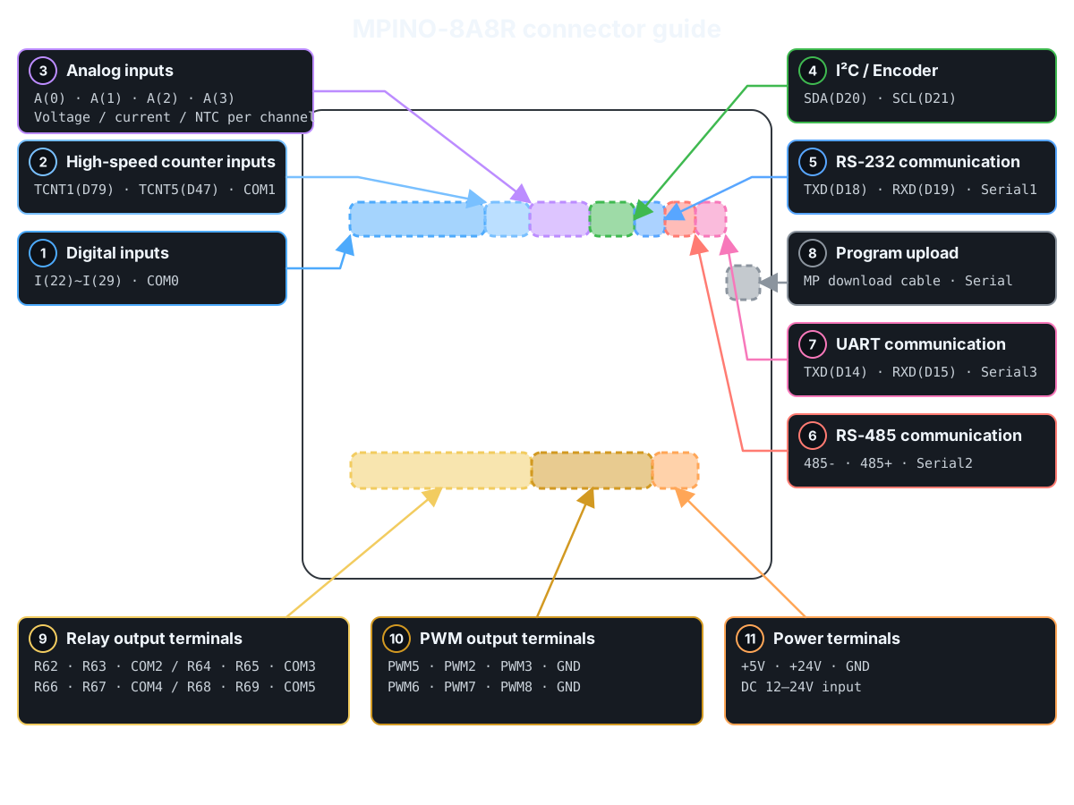
## Product Specifications
| Category | Quantity | Terminal / Item | Specifications |
| — | — | — | — |
| Power | - | Supply voltage | DC 12~24V (0.5A or more when using DC 24V) |
| Digital inputs | 8 points (Solid-state, isolated) | I(22)~I(29) | operating input voltage: DC 0~40V HIGH detection voltage: DC 5V or higher input resistance: 2.2kΩ 8 points/1COM NPN/PNP input support |
| Relay outputs | 8 points (Mechanical contacts, isolated) | R(62)~R(69) | operating connection voltage: DC 0~30V or AC 0~250V maximum allowable output current: 5A/1 points 2 points/1COM × 4 groups |
| Analog inputs | 4 points (Non-isolated) | A(0)~A(3) | Select DC 0~5V, DC 0~10V, DC 0~20mA or NTC 10kΩ(25℃) per channel resolution: 10bit (0~1023) Input resistance: 2kΩ(0~5V), 4kΩ(0~10V), 250Ω(current), 10kΩ pull-up(NTC) |
| High-speed counter inputs | 2 points (Solid-state, isolated) | TCNT1, TCNT5 | operating input voltage: DC 0~80V HIGH detection voltage: DC 3V or higher maximum input frequency: 5kHz Use TIMER1·TIMER5 |
| Interrupt inputs | 4 points (Non-isolated) | PWM2(D2), PWM3(D3) SDA(D20), SCL(D21) | input voltage: DC 0~5V HIGH detection voltage: DC 3V or higher PWM2/PWM3: no pull-up or pull-down SDA/SCL: built-in 4.7kΩ pull-up |
| PWM outputs | 6 points (Non-isolated) | PWM5(D5), PWM2(D2), PWM3(D3) PWM6(D6), PWM7(D7), PWM8(D8) | output voltage: LOW(DC 0V), HIGH(DC 5V) maximum output current: 30mA Built-in 150Ω protection resistor |
| Communication Channels | 1 channel (Non-isolated) | I²C | I²C master/slave supported Use SDA(D20), SCL(D21) |
| RS-232 | Use `Serial1` Built-in Modbus RTU Master & Slave commands supported Built-in LS Industrial Systems Cnet commands supported | ||
| RS-485 | Use `Serial2` Automatic direction control supported Built-in Modbus RTU Master & Slave commands supported Built-in LS Industrial Systems Cnet commands supported | ||
| UART | Use `Serial3` Built-in Modbus RTU Master & Slave commands supported Built-in LS Industrial Systems Cnet commands supported | ||
| Memory | - | Flash | 256KB (including 8KB BootLoader) |
| SRAM | 8KB | ||
| EEPROM | 4KB |
## Digital inputs
[See the one-channel digital-input check before wiring for the first time. →](https://www.ilogics.net/docs/en-us_guide:wiring#digital_input_one_channel_check “en-us_guide:wiring”)
| Group | Terminal | Arduino Pin | Input Configuration | Terminals and Wiring Example |
| — | — | — | — | — |
| COM0 | I(22)~I(29) | D22~D29 | 8 digital inputs, sharing COM0 | [MPINO-8A8R digital input terminals and NPN/PNP wiring](https://www.ilogics.net/docs/_media/en-us_products:mpino-8a8r-digital-input.svg “en-us_products:mpino-8a8r-digital-input.svg”) |
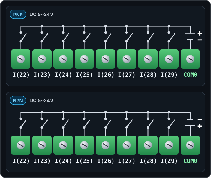
The digital inputs are isolated by bidirectional optocouplers and accept DC 5~24V NPN or PNP signals. Select the input type through the COM0 wiring polarity.
### Example program · digital inputs
Use digitalRead() to display the D22~D29 input states every 200ms. HIGH is 1 and LOW is 0.
```cpp void setup() {
Serial.begin(115200);
}
void loop() {
for (uint8_t pin = 22; pin <= 29; pin++) {
  Serial.print(F("D"));
  Serial.print(pin);
  Serial.print(F(": "));
  Serial.println(digitalRead(pin));
}
delay(200);
} ```
Related built-in functions
#### Function example · consecutive-read filter: IdigitalRead()
Function prototype
```cpp bool IdigitalRead(uint8_t pin, uint8_t samples); ```
IdigitalRead(22, 5) reads D22 5 times consecutively. Update the state when all readings are HIGH or all are LOW; mixed readings retain the previous state. Unlike a time-based debounce filter, it inserts no delay between readings.
```cpp void setup() {
Serial.begin(115200);
}
void loop() {
const bool inputOn = IdigitalRead(22, 5);  // Read D22 five times consecutively and return the stable state
Serial.println(inputOn ? F("D22 ON") : F("D22 OFF"));
delay(200);
} ```
#### Function example · debouncing: Ibounce(), IbounceOn(), IbounceOff()
Function prototype
```cpp bool Ibounce(uint8_t pin, uint32_t debounceTime); bool IbounceOn(uint8_t pin, uint32_t debounceTime); bool IbounceOff(uint8_t pin, uint32_t debounceTime); ```
Compare three filters on the D22 input. Each returns the filtered ON/OFF state.
- `Ibounce(22, 30)`: Apply ON and OFF only after they remain stable for at least 30ms. - `IbounceOn(22, 500)`: Delay ON by 500ms; apply OFF immediately. - `IbounceOff(22, 500)`: Delay OFF by 500ms; apply ON immediately.
Each function operates independently, even on the same pin. Run the filters on every loop() iteration and display only the results at 200ms intervals.
```cpp unsigned long lastPrint = 0;
void setup() {
Serial.begin(115200);
}
void loop() {
const bool stable = Ibounce(22, 30);  // Filter D22 ON/OFF chatter over 30ms
const bool onDelayed = IbounceOn(22, 500);  // Delay only D22 ON by 500ms; apply OFF immediately
const bool offDelayed = IbounceOff(22, 500);  // Delay only D22 OFF by 500ms; apply ON immediately
if (millis() - lastPrint >= 200) {
  lastPrint = millis();
  Serial.print(F("Ibounce: "));
  Serial.print(stable);
  Serial.print(F(", IbounceOn: "));
  Serial.print(onDelayed);
  Serial.print(F(", IbounceOff: "));
  Serial.println(offDelayed);
}
} ```
#### Function example · input toggle: Ialt()
Function prototype
```cpp void Ialt(bool input, bool &state_var); ```
Ialt(input, state) inverts state whenever the input changes from OFF to ON. Pressing D22 once turns D62 ON; pressing again turns it OFF. Holding the input retains the state. The example debounces the input with Ibounce(22, 30) before passing it to Ialt(). outputOn is a global variable retained between calls, and Ialt() modifies it directly.
```cpp bool outputOn = false;
void setup() {
Serial.begin(115200);
digitalWrite(62, LOW);
}
void loop() {
const bool previous = outputOn;
const bool inputOn = Ibounce(22, 30);  // Filter D22 ON/OFF chatter over 30ms
Ialt(inputOn, outputOn);  // Invert outputOn on an OFF→ON input transition
digitalWrite(62, outputOn ? HIGH : LOW);
if (outputOn != previous) {
  Serial.println(outputOn ? F("D62 ON") : F("D62 OFF"));
}
} ```
## Relay outputs
[See the one-channel relay-output check before wiring for the first time. →](https://www.ilogics.net/docs/en-us_guide:wiring#relay_output_one_channel_check “en-us_guide:wiring”)
| Group | Terminal | Arduino Pin | Contact ratings | Terminals and Wiring Example |
| — | — | — | — | — |
| COM2 | R(62), R(63) | D62, D63 | AC 250V or DC 30V, Max. 5A/1 points | [MPINO-8A8R relay output terminals and load wiring](https://www.ilogics.net/docs/_media/en-us_products:mpino-8a8r-relay-output.svg “en-us_products:mpino-8a8r-relay-output.svg”) |
| COM3 | R(64), R(65) | D64, D65 | AC 250V or DC 30V, Max. 5A/1 points | |
| COM4 | R(66), R(67) | D66, D67 | AC 250V or DC 30V, Max. 5A/1 points | |
| COM5 | R(68), R(69) | D68, D69 | AC 250V or DC 30V, Max. 5A/1 points |
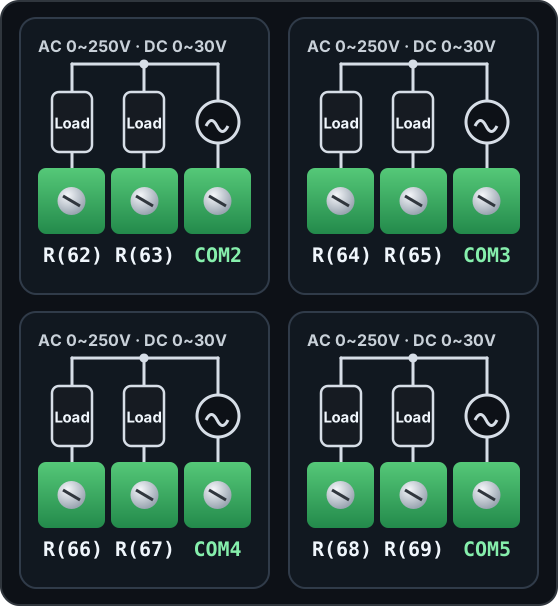
Relay outputs are dry contacts that physically connect each COM terminal to its output terminal. Connect a separate load power supply.
### Example program · relay outputs
Map inputs D22~D29 to outputs D62~D69 in order. When an input is HIGH, its corresponding output turns ON.
```cpp void setup() {
for (uint8_t pin = 62; pin <= 69; pin++) digitalWrite(pin, LOW);
}
void loop() {
for (uint8_t ch = 0; ch < 8; ch++) {
  digitalWrite(62 + ch, digitalRead(22 + ch));
}
} ```
## Analog Input
| Selected mode | Input Range | Input resistance | Connector Pinout |
| — | — | — | — |
| Voltage input | DC 0~5V | 2kΩ | [MPINO-8A8R analog input connector pinout](https://www.ilogics.net/docs/_media/en-us_products:mpino-8a8r-analog-input.svg “en-us_products:mpino-8a8r-analog-input.svg”) |
| Voltage input | DC 0~10V | 4kΩ | |
| Current input | DC 0~20mA | 250Ω | |
| NTC temperature sensor | NTC 10kΩ(25℃), 3950K | 10kΩ pull-up |
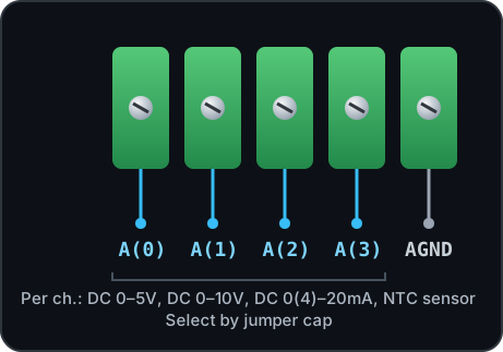
For A(0)~A(3), select each input range using the channel jumper position.
### Example program · analog inputs
Use analogRead() to display the ADC raw values (0~1023) of A0~A3. Each channel's voltage/current mode follows the actual product settings.
```cpp const uint8_t analogPins[] = {A0, A1, A2, A3};
void setup() {
Serial.begin(115200);
}
void loop() {
for (uint8_t ch = 0; ch < 4; ch++) {
  Serial.print(F("A"));
  Serial.print(ch);
  Serial.print(F(" ADC: "));
  Serial.println(analogRead(analogPins[ch]));
}
delay(500);
} ```
Related built-in functions
#### Function example · input range scaling: IanalogRead(), IanalogReadf()
Function prototype
```cpp int32_t IanalogRead(uint8_t ch, int32_t min, int32_t max); float IanalogReadf(uint8_t ch, float min, float max); ```
This example assumes A0 is configured for 0~5V input and A2 for 0(4)~20mA input. Both functions scale the ADC input to the specified min~max range. IanalogRead() returns an integer with the fractional part discarded; IanalogReadf() returns a floating-point value. This example displays the 0~5V input on A0 as both 0~100% and voltage. For the 0~20mA input on A2, specify a range of 0~20 to read the actual current.
```cpp void setup() {
Serial.begin(115200);
}
void loop() {
const int32_t percent = IanalogRead(A0, 0, 100);  // Scale A0 to an integer from 0~100%
const float voltage = IanalogReadf(A0, 0.0f, 5.0f);  // Scale A0 to a floating-point voltage from 0~5V
const float current = IanalogReadf(A2, 0.0f, 20.0f);  // Scale A2 to a floating-point current from 0~20mA
Serial.print(F("A0: "));
Serial.print(percent);
Serial.print(F(" %, "));
Serial.print(voltage, 2);
Serial.print(F(" V, A2: "));
Serial.print(current, 2);
Serial.println(F(" mA"));
delay(500);
} ```
#### Function example · 4~20mA range scaling: IanalogRead2(), IanalogRead2f()
Function prototype
```cpp int32_t IanalogRead2(uint8_t ch, int32_t min, int32_t max); float IanalogRead2f(uint8_t ch, float min, float max); ```
This example assumes A0 is configured for 0~5V input and A2 for 0(4)~20mA input. Scale a 4~20mA sensor input connected to A2 to a user-defined range. IanalogRead2(A2, 0, 100) returns an integer with 4mA mapped to 0% and 20mA to 100%. IanalogRead2f(A2, 4.0f, 20.0f) returns the current as a floating-point value. Below approximately 3.6mA, both functions return ANALOG\_READ2\_ERROR(65535); from approximately 3.6~4mA, they return the specified minimum.
```cpp void setup() {
Serial.begin(115200);
}
void loop() {
const int32_t percent = IanalogRead2(A2, 0, 100);  // Scale A2 4~20mA to an integer from 0~100%
const float current = IanalogRead2f(A2, 4.0f, 20.0f);  // Convert A2 4~20mA to a floating-point current
if (percent == ANALOG_READ2_ERROR ||
    current == (float)ANALOG_READ2_ERROR) {
  Serial.println(F("A2: 4-20mA input error"));
} else {
  Serial.print(F("A2: "));
  Serial.print(percent);
  Serial.print(F(" %, "));
  Serial.print(current, 2);
  Serial.println(F(" mA"));
}
delay(500);
} ```
#### Function example · moving average: analogReadAvg(), analogRead2Avg()
Function prototype
```cpp int32_t analogReadAvg(uint8_t ch, uint8_t samples); int32_t analogRead2Avg(uint8_t ch, uint8_t samples); ```
This example assumes A0 is configured for 0~5V input and A2 for 0(4)~20mA input. analogReadAvg(A0, 5) returns a moving average of the raw A0 ADC readings (0~1023). analogRead2Avg(A2, 5) averages the corrected A2 4~20mA values (4mA=0, 20mA=32767). Each function accumulates up to 5 valid readings from recent calls; it does not take 5 readings in one call. The maximum samples value is 20. analogRead2Avg() returns ANALOG\_READ2\_AVG\_ERROR(-1) for inputs below approximately 3.6mA.
```cpp void setup() {
Serial.begin(115200);
}
void loop() {
const int32_t voltageAvg = analogReadAvg(A0, 5);  // Moving average of up to 5 recent A0 ADC values
const int32_t currentAvg = analogRead2Avg(A2, 5);  // Moving average of up to 5 recent corrected A2 4~20mA values
Serial.print(F("A0 ADC average: "));
Serial.print(voltageAvg);
Serial.print(F(", A2 4-20mA average: "));
if (currentAvg == ANALOG_READ2_AVG_ERROR) {
  Serial.println(F("input error"));
} else {
  Serial.println(currentAvg);
}
delay(500);
} ```
### Example program · temperature sensor inputs
Run this only on products with A0 configured for NTC input. Use analogRead() to display the temperature-sensor ADC raw value (0~1023) of A0. Celsius conversion is explained in the built-in functions below.
```cpp void setup() {
Serial.begin(115200);
}
void loop() {
Serial.print(F("A0 ADC: "));
Serial.println(analogRead(A0));
delay(500);
} ```
Related built-in functions
#### Function example · read NTC temperature: ntcRead(), ntcReadf()
Function prototype
```cpp int ntcRead(uint8_t ch); float ntcReadf(uint8_t ch); ```
Run this only on products with channel A0 configured for NTC input. Read the temperature of the NTC 10kΩ (25℃), B=3950K sensor connected to NTC input A0. ntcRead() returns an integer equal to 10 times the Celsius temperature (25.3℃ → 253); ntcReadf() returns the Celsius temperature as a floating-point value (25.3). Both have a resolution of 0.1℃. Values outside the conversion range are clamped to -40℃ or 120℃, so do not use these values to detect an open or short circuit.
```cpp void setup() {
Serial.begin(115200);
}
void loop() {
const int temperature10 = ntcRead(A0);  // Return A0 temperature as an integer in Celsius ×10
const float temperature = ntcReadf(A0);  // Return A0 temperature as floating-point Celsius
Serial.print(F("ntcRead: "));
Serial.print(temperature10);
Serial.print(F(" (0.1 C), ntcReadf: "));
Serial.print(temperature, 1);
Serial.println(F(" C"));
delay(500);
} ```
## High-speed counter / Interrupts / Encoder
| Function | Terminals / Arduino pins | channel |
| — | — | — |
| Isolated high-speed counter | TCNT1(D79), TCNT5(D47), COM1 | 2 points |
| External interrupts | PWM2(D2), PWM3(D3), SDA(D20), SCL(D21) | 4 points |
| Encoder Inputs | Phase A: SDA(D20), phase B: SCL(D21) | 1 channel |
TCNT1 and TCNT5 are used as external clock inputs for TIMER1·TIMER5. I²C communication cannot be used simultaneously when SDA and SCL are used as encoder inputs.
### Example program · pulse counting
Count the TCNT1·TCNT5 isolated inputs as external timer clocks. Use rising edges on the MCU timer input; the value wraps to 0 after 65535. Read atomically and display every 500ms.
```cpp #include <util/atomic.h>
void setup() {
Serial.begin(115200);
TIMSK1 = 0;
TCCR1A = 0;
TCCR1B = 0x07;
TCNT1 = 0;
TIMSK5 = 0;
TCCR5A = 0;
TCCR5B = 0x07;
TCNT5 = 0;
}
void loop() {
uint16_t first, second;
ATOMIC_BLOCK(ATOMIC_RESTORESTATE) {
  first = TCNT1;
  second = TCNT5;
}
Serial.print(F("TCNT1: "));
Serial.print(first);
Serial.print(F(", TCNT5: "));
Serial.println(second);
delay(500);
} ```
Count FALLING edges on SDA(D20). The inputs have 4.7kΩ pull-ups (SDA/SCL). This software interrupt example reads the 32-bit value with ATOMIC\_BLOCK and displays it every 500ms. Lossless counting is not guaranteed at the maximum input frequency. Because this uses SDA·SCL, do not run it simultaneously with I²C communication.
```cpp static_assert(digitalPinToInterrupt(SDA) != NOT_AN_INTERRUPT, “Invalid interrupt input”);
#include <util/atomic.h>
volatile uint32_t pulseCount = 0;
void countPulse() {
pulseCount++;
}
void setup() {
Serial.begin(115200);
// SDA is pulled up; count when the external signal pulls it to GND
attachInterrupt(digitalPinToInterrupt(SDA), countPulse, FALLING);
}
void loop() {
uint32_t snapshot;
ATOMIC_BLOCK(ATOMIC_RESTORESTATE) {
  snapshot = pulseCount;
}
Serial.print(F("SDA pulses: "));
Serial.println(snapshot);
delay(500);
} ```
Related built-in functions
#### Function example · configure hardware pulse counter: TCNTSETUP()
Function prototype
```cpp void TCNTSETUP(uint8_t timerNumber, bool on32bit = false); ```
Use TCNTSETUP(timerNumber, false) to configure Timer1·Timer5 as 16-bit external-clock counters. Read the accumulated values from the TCNT1·TCNT5 registers. TCNTOUT() returns the overflow count in 32-bit mode, not the accumulated pulse count, so it is not used in this 16-bit example. Do not reconfigure Timer1·Timer5 with other timer functions.
```cpp #include <util/atomic.h>
void setup() {
Serial.begin(115200);
TCNTSETUP(1, false);  // Configure Timer1 as a 16-bit external pulse counter
TCNTSETUP(5, false);  // Configure Timer5 as a 16-bit external pulse counter
}
void loop() {
uint16_t first, second;
ATOMIC_BLOCK(ATOMIC_RESTORESTATE) {
  first = TCNT1;
  second = TCNT5;
}
Serial.print(F("TCNT1: "));
Serial.print(first);
Serial.print(F(", TCNT5: "));
Serial.println(second);
delay(500);
} ```
### Example program · encoder inputs
Connect phase A to SDA(D20) and phase B to SCL(D21). This x1 counting example uses a 4.7kΩ pull-up (SDA/SCL) and increments when phase B is LOW at a FALLING edge. The actual rotation direction depends on the phase A/B wiring. Because this uses SDA·SCL, do not run it simultaneously with I²C communication.
```cpp static_assert(digitalPinToInterrupt(SDA) != NOT_AN_INTERRUPT, “Invalid interrupt input”);
#include <util/atomic.h> #include <stdint.h>
volatile int32_t position = 0;
void readEncoder() {
// Increment if phase B is LOW at the phase A falling edge (x1 decoding)
if (digitalRead(SCL) == LOW) {
  if (position < INT32_MAX) position++;
} else {
  if (position > INT32_MIN) position--;
}
}
void setup() {
Serial.begin(115200);
// Encoder phase A → SDA(D20), phase B → SCL(D21)
attachInterrupt(digitalPinToInterrupt(SDA), readEncoder, FALLING);
}
void loop() {
int32_t snapshot;
ATOMIC_BLOCK(ATOMIC_RESTORESTATE) {
  snapshot = position;
}
Serial.print(F("Encoder: "));
Serial.println(snapshot);
delay(500);
} ```
## PWM Output
| Terminal | Arduino Pin | Timers | Connector Pinout |
| — | — | — | — |
| PWM5, PWM2, PWM3 | D5, D2, D3 | TIMER3 | [MPINO-8A8R PWM output connector pinout](https://www.ilogics.net/docs/_media/en-us_products:mpino-8a8r-pwm-output.svg “en-us_products:mpino-8a8r-pwm-output.svg”) |
| PWM6, PWM7, PWM8 | D6, D7, D8 | TIMER4 |
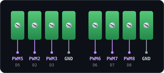
PWM outputs use an 8bit duty value by default, with an output voltage of DC 0~5V. PWM2 and PWM3 share interrupt-input functions.
### Example program · PWM outputs
Set analogWrite() duty value 128 in the 0~255 range on D5, D2, D3, D6, D7, D8 to output approximately 50% PWM.
```cpp void setup() {
analogWrite(5, 128);
analogWrite(2, 128);
analogWrite(3, 128);
analogWrite(6, 128);
analogWrite(7, 128);
analogWrite(8, 128);
}
void loop() { } ```
Related built-in functions
#### Function example · specify duty value: PWM()
Function prototype
```cpp void PWM(uint8_t pin, uint16_t val, bool onDutybit16 = false); ```
PWM(pin, val, onDutybit16) sets the duty value. The 8-bit range is 0~255; with the third argument true, the 16-bit range is 0~65535. Output the 16-bit midpoint value 32768 on D5. D5·D2·D3 share Timer3, and D6·D7·D8 share Timer4; use the same resolution on the same timer. Start after calling PWM\_RESET().
```cpp void setup() {
PWM_RESET();  // Stop PWM timers and reset their modes
PWM(5, 32768, true);  // Output a midrange 16-bit duty value on D5
}
void loop() { } ```
#### Function example · set frequency/duty: FDPWM()
Function prototype
```cpp void FDPWM(uint8_t pin, int32_t intHz, float Duty); ```
FDPWM(pin, intHz, Duty) specifies the frequency (Hz) and duty cycle (%). Output 1kHz at 50% duty on D5. D5·D2·D3 share Timer3, and D6·D7·D8 share Timer4; specify the same frequency for outputs on the same timer. There is no separate FPWM() function; use FDPWM(pin, hz, 50.0f) for 50% duty output.
```cpp void setup() {
PWM_RESET();  // Stop PWM timers and reset their modes
FDPWM(5, 1000, 50.0f);  // Output 1kHz at 50% duty on D5
}
void loop() { } ```
#### Function example · output a specified pulse count: NPWM\_BEGIN(), NPWM()
Function prototype
```cpp void NPWM_BEGIN(uint8_t pin, uint32_t intHz, float Duty, uint32_t N); void NPWM(uint8_t pin); ```
Use NPWM\_BEGIN() to prepare 100 pulses at 1kHz and 50% duty on D5, then run NPWM() on every loop() iteration to handle output and completion. Do not insert delay(). D5·D2·D3 share Timer3, and D6·D7·D8 share Timer4; do not combine this with other outputs on the same timer.
```cpp void setup() {
PWM_RESET();  // Stop PWM timers and reset their modes
NPWM_BEGIN(5, 1000, 50.0f, 100);  // Prepare 100 pulses at 1kHz, 50% duty on D5
}
void loop() {
NPWM(5); // Process the prepared pulse output and completion
} ```
#### Function example · stop/resume channel output: PWMOFF()
Function prototype
```cpp void PWMOFF(uint8_t pin, bool POff); ```
PWMOFF(pin, true) sets the channel stop flag; false clears it. Call FDPWM() immediately after setting the flag to apply it to the output connection. Turn D5 on for 2 seconds and off for 2 seconds; after stopping, hold LOW with digitalWrite(). This stop flag does not apply to NPWM().
```cpp void setup() {
PWM_RESET(); // Stop PWM timers and reset their modes
}
void loop() {
PWMOFF(5, false);  // Clear the stop state of D5
FDPWM(5, 1000, 50.0f);  // Apply the cleared flag and start 1kHz, 50% output
delay(2000);
PWMOFF(5, true); // Set the stop state of D5
FDPWM(5, 1000, 50.0f);  // Apply the stop flag and disconnect PWM output
digitalWrite(5, LOW);
delay(2000);
} ```
#### Function example · stop/reset PWM timers: PWM\_RESET()
Function prototype
```cpp void PWM_RESET(); ```
PWM\_RESET() resets the Timer1·Timer3·Timer4·Timer5 control registers and counters. Output 1kHz on D5 for 2 seconds, then stop all timers. This also affects PWM and counters on the same timer. It does not also clear the PWMOFF() stop flag.
```cpp void setup() {
PWM_RESET();  // Stop PWM timers and reset their modes
FDPWM(5, 1000, 50.0f);  // Output 1kHz at 50% duty on D5
delay(2000);
PWM_RESET();  // Stop and reset all PWM on Timer1, Timer3, Timer4 and Timer5
digitalWrite(5, LOW);
}
void loop() { } ```
## Communication and Upload
| Function | Arduino Pin | Object | Device Wiring |
| — | — | — | — |
| Program upload and monitoring | D0(RX0), D1(TX0) | `Serial` | [MPINO-8A8R communication connectors and device wiring](https://www.ilogics.net/docs/_media/en-us_products:mpino-8a8r-communication.svg “en-us_products:mpino-8a8r-communication.svg”) |
| RS-232 | D19(RX1), D18(TX1) | `Serial1` | |
| RS-485 | D17(RX2), D16(TX2) | `Serial2` | |
| UART | D15(RX3), D14(TX3) | `Serial3` | |
| I²C | D20(SDA), D21(SCL) | `Wire` |
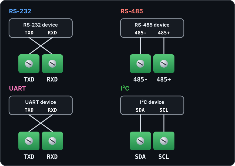
Use the MP download cable to upload programs. RS-485 uses automatic direction control, so no separate control pin is needed to switch between transmission and reception.
### Example program · basic communication
Forward characters between Serial(115200bps) and RS-232 Serial1(9600bps, 8-N-1). Check the free space in the transmit buffer with availableForWrite(). Serial2 is RS-485 and Serial3 is TTL UART; when using those terminals, replace Serial1 in the example with the corresponding object.
```cpp // Serial Monitor via MP download cable ↔ RS-232 Serial1 void setup() {
Serial.begin(115200);
Serial1.begin(9600);  // Also configure the other device for 9600 bps, 8-N-1
}
void loop() {
if (Serial.available() && Serial1.availableForWrite()) {
  Serial1.write(Serial.read());
}
if (Serial1.available() && Serial.availableForWrite()) {
  Serial.write(Serial1.read());
}
} ```
### Example program · I²C communication
Use Wire to scan addresses 0x08~0x77 and display responding addresses every 3 seconds. Do not run this simultaneously with encoder/interrupt examples that use SDA·SCL.
```cpp #include <Wire.h>
void setup() {
Serial.begin(115200);
Wire.begin();
Wire.setClock(100000);
}
void loop() {
uint8_t found = 0;
for (uint8_t address = 0x08; address <= 0x77; address++) {
  Wire.beginTransmission(address);
  const uint8_t result = Wire.endTransmission();
  if (result == 0) {
    Serial.print(F("I2C: 0x"));
    if (address < 16) Serial.print('0');
    Serial.println(address, HEX);
    found++;
  }
}
Serial.print(F("Devices: "));
Serial.println(found);
delay(3000);
} ```
### Example program · Modbus RTU communication
Related built-in functions
#### Function example · Modbus RTU Slave: ImodbusRTUMem(), ImodbusRTUAdr(), ImodbusRTUInit(), ImodbusRTU()
Function prototype
```cpp void ImodbusRTUMem(uint16_t m_size, uint16_t d_size); void ImodbusRTUAdr(uint16_t m_offset, uint16_t d_offset); void ImodbusRTUInit(HardwareSerial& serialPort, uint8_t slaveId, long baudrate); void ImodbusRTU(); ```
Store the D22 state in M[0] and the raw A0 reading (0~1023) in D[0] for the other device to read. Configure RS-232(Serial1), station 1, 9600bps, 8N1. Read M[0] with FC01, start address 0, quantity 1 bit; read D[0] with FC03, start address 0, quantity 1 word. Addresses are zero-based on-wire addresses. Call the communication function on every loop() iteration. This example does not control outputs.
M and D are shared global memory provided by the core. Run this sketch on its own. When combining protocols, do not allocate the shared memory more than once. For RS-485 terminals, replace Serial1 with Serial2; for UART terminals, use Serial3.
```cpp unsigned long lastPrint = 0; bool memoryReady = false;
void setup() {
Serial.begin(115200);
ImodbusRTUMem(8, 8);  // Allocate 8 M bits and 8 D words
ImodbusRTUAdr(0, 0);  // Set the M and D communication start addresses to 0
ImodbusRTUInit(Serial1, 1, 9600);  // Start RS-232 at station 1, 9600bps
memoryReady = (M != nullptr && D != nullptr);
if (!memoryReady) Serial.println(F("Memory allocation failed"));
}
void loop() {
if (!memoryReady) return;
M[0] = digitalRead(22);
D[0] = analogRead(A0);
ImodbusRTU();  // Process incoming Modbus RTU requests
if (millis() - lastPrint >= 1000) {
  lastPrint = millis();
  Serial.print(F("M[0]: "));
  Serial.print(M[0]);
  Serial.print(F(", D[0]: "));
  Serial.println(D[0]);
}
} ```
#### Function example · Modbus RTU Master: ImodbusRTUmasterInit(), ImodbusRTUmaster()
Function prototype
```cpp void ImodbusRTUmasterInit(HardwareSerial& serialPort, long baudrate, uint8_t config); uint8_t ImodbusRTUmaster(HardwareSerial& serialPort, uint8_t slaveId, uint8_t functionCode, uint16_t address, uint16_t quantity, uint16_t* data, uint16_t timeoutMs = 100); ```
Read one holding register from the remote slave over RS-232(Serial1) every 1 second. Configure the other device for station 1, 9600bps, 8N1, FC03, and on-wire start address 0. The response is stored in received[0] and displayed only on success. Error codes are displayed in hexadecimal. This is a separate sketch from the slave example above and uses a receive array instead of M/D memory. For RS-485 terminals, replace Serial1 with Serial2; for UART terminals, use Serial3.
```cpp unsigned long lastRequest = 0; uint16_t received[1];
void setup() {
Serial.begin(115200);
ImodbusRTUmasterInit(Serial1, 9600, SERIAL_8N1);  // Start RS-232 as a Modbus master
}
void loop() {
if (millis() - lastRequest < 1000) return;
lastRequest = millis();
const uint8_t result = ImodbusRTUmaster(Serial1, 1, 3, 0, 1, received, 200);  // Read 1 word at address 0 from station 1, timeout 200ms
if (result == IMODBUS_RTU_SUCCESS) {
  Serial.print(F("Register 0: "));
  Serial.println(received[0]);
} else {
  Serial.print(F("Modbus error: 0x"));
  Serial.println(result, HEX);
}
} ```
### Example program · LS Industrial Systems Cnet communication
Related built-in functions
#### Function example · LS Industrial Systems Cnet SLave: ICnetMem(), ICnetAdr(), ICnetInit(), ICnet()
Function prototype
```cpp void ICnetMem(uint16_t m_size, uint16_t d_size, uint16_t r_size = 100); void ICnetAdr(uint16_t m_offset, uint16_t d_offset, uint16_t r_offset = 0); void ICnetInit(HardwareSerial& serialPort, uint8_t slaveId, long baudrate); void ICnet(); ```
Store the D22 state in M[0] and the raw A0 reading (0~1023) in D[0] for an HMI to read. Configure the other device for LS Industrial Systems Cnet, RS-232, station 1, 9600bps, 8N1. Read the bit at %MX00000(M[0]) and the word at %DW0(D[0]). Call the communication function on every loop() iteration. This example does not control outputs.
M, D, and R are shared global memory provided by the core; this example does not use R. Run this separately from the Modbus example. When combining protocols, do not allocate the shared memory more than once. For RS-485 terminals, replace Serial1 with Serial2; for UART terminals, use Serial3.
```cpp unsigned long lastPrint = 0; bool memoryReady = false;
void setup() {
Serial.begin(115200);
ICnetMem(8, 8, 0);  // Allocate 8 M bits and 8 D words; R is unused
ICnetAdr(0, 0, 0);  // Set the M and D communication start addresses to 0
ICnetInit(Serial1, 1, 9600);  // Start RS-232 at station 1, 9600bps
memoryReady = (M != nullptr && D != nullptr);
if (!memoryReady) Serial.println(F("Memory allocation failed"));
}
void loop() {
if (!memoryReady) return;
M[0] = digitalRead(22);
D[0] = analogRead(A0);
ICnet();  // Process incoming LS Cnet requests
if (millis() - lastPrint >= 1000) {
  lastPrint = millis();
  Serial.print(F("M[0]: "));
  Serial.print(M[0]);
  Serial.print(F(", D[0]: "));
  Serial.println(D[0]);
}
} ```
[MPINO Series comparison](https://www.ilogics.net/docs/en-us_products:mpino_series “en-us_products:mpino_series”)
[Online product details](https://www.ilogics.net/docs/en-us/products:mpino_8a8r)