
This is an old revision of the document!
Table of Contents
MPINO-8A4T-S
MPINO-8A4T-S is an all-in-one industrial Arduino controller with 8 digital inputs and 4 SINK transistor outputs. A single PCB integrates voltage and current analog inputs, NTC temperature sensor inputs, PWM, high-speed inputs, and RS-232 communication.
Program the controller with Arduino IDE (Arduino C/C++) or MPINO STUDIO 2 (Arduino C/C++ & ladder logic).
See the MPINO Arduino IDE settings for the board name, connection method, and first I/O numbers for MPINO-8A4T-S.
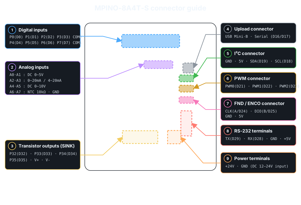
Product Specifications
| Category | Quantity | Terminal / Item | Specifications |
|---|---|---|---|
| Power | - | Supply voltage | DC 12~24V (0.5A or more when using DC 24V) |
| Digital inputs | 8 points (Solid-state, isolated) | P0~P7 | operating input voltage: DC 0~40V HIGH detection voltage: DC 5V or higher 8 points/1COM NPN/PNP input support |
| Transistor outputs | 4 points (Solid-state, isolated) | P32~P35 | Output type: SINK Output operation: connected to V- when ON maximum allowable output current: 1A/1 points load voltage: DC 0~100V Connect the load supply to V+ and V- |
| Analog inputs | 2 points (Non-isolated) | A0, A1 | input voltage: DC 0~5V resolution: 10bit (0~1023) input resistance: 100MΩ (±1%) |
| Analog inputs | 2 points (Non-isolated) | A2, A3 | input current: 0~20mA or 4~20mA Resolution: 0~20mA is 10bit (0~1023); 4~20mA is 0~818 input resistance: 250Ω (±1%) |
| Analog inputs | 2 points (Non-isolated) | A4, A5 | input voltage: DC 0~10V resolution: 10bit (0~1023) input resistance: 200kΩ (±1%) |
| Temperature sensor inputs | 2 points (Non-isolated) | NTEMP A6, A7 | input temperature: -40~120℃ Sensor: NTC 3950K, 10kΩ(25℃) Resolution: 0.1℃ (at 0~40℃) |
| Interrupts High-Speed Counter / Encoder | 4 points (Non-isolated) | D24(CLK), D25(DIO) D18(SCL), D19(SDA) | input voltage: DC 0~5V HIGH detection voltage: DC 3V or higher input frequency: Max. 50kHz D24/D25: built-in 4.7kΩ pull-up D18/D19: built-in 4.7kΩ pull-up |
| Pulse outputs | 3 points (Non-isolated) | PWM D21, D22, D23 | output voltage: LOW(DC 0V), HIGH(DC 5V) maximum output current: 30mA |
| Communication Channels | 1 channel (Non-isolated) | I²C | I²C master/slave supported Can be used as interrupt ports (4.7kΩ pull-up) |
| RS-232 | Uses Serial1 Built-in Modbus RTU Master & Slave commands supported Built-in LS Industrial Systems Cnet commands supported |
||
| Memory | - | Flash | 128KB |
| SRAM | 4KB | ||
| EEPROM | 4KB |
Digital inputs
See the one-channel digital-input check before wiring for the first time. →
| Terminal | Arduino Pin | Input Configuration | Terminals and Wiring Example |
|---|---|---|---|
| P0~P3 | D0~D3 | 4 digital inputs, sharing COM0 |  |
| P4~P7 | D4~D7 | 4 digital inputs, sharing COM1 |
The digital inputs are isolated by optocouplers and accept DC 5~24V NPN or PNP signals. Select the input type by wiring the COM terminal accordingly.
Example program · digital inputs
Read P0~P7 with digitalRead() and display their states in the Serial Monitor every 200ms. HIGH is displayed as 1 and LOW as 0.
// MPINO-8A4T-S: display P0~P7 input states in the serial monitor.
void setup() {
  Serial.begin(115200);
}

void loop() {
  for (uint8_t pin = 0; pin < 8; pin++) {
    Serial.print('P');
    Serial.print(pin);
    Serial.print('=');
    Serial.print(digitalRead(pin));
    Serial.print(' ');
  }
  Serial.println();
  delay(200);
}
Related built-in functions
Function example · consecutive-read filter: IdigitalRead()
Function prototype
bool IdigitalRead(uint8_t pin, uint8_t samples);
IdigitalRead(0, 5) reads P0 5 times consecutively. It updates the state when all readings are HIGH or all are LOW; mixed readings retain the previous state. Unlike a time-based debounce filter, it inserts no delay between readings.
void setup() {
  Serial.begin(115200);
}

void loop() {
  const bool inputOn = IdigitalRead(0, 5);  // Return the stable state after 5 consecutive P0 readings
  Serial.println(inputOn ? F("P0 ON") : F("P0 OFF"));
  delay(200);
}
Function example · debouncing: Ibounce(), IbounceOn(), IbounceOff()
Function prototype
bool Ibounce(uint8_t pin, uint32_t debounceTime);
bool IbounceOn(uint8_t pin, uint32_t debounceTime);
bool IbounceOff(uint8_t pin, uint32_t debounceTime);
Compare three filters on the P0 input. Each returns the filtered ON/OFF state.
Ibounce(0, 30): Apply either ON or OFF after it remains stable for at least 30ms.IbounceOn(0, 500): Delay ON by 500ms; apply OFF immediately.IbounceOff(0, 500): Delay OFF by 500ms; apply ON immediately.
Each function operates independently, even on the same pin. Run the filters on every loop() iteration and display only the results at 200ms intervals.
unsigned long lastPrint = 0;

void setup() {
  Serial.begin(115200);
}

void loop() {
  const bool stable = Ibounce(0, 30);  // Debounce P0 ON/OFF transitions for 30ms
  const bool onDelayed = IbounceOn(0, 500);  // Delay P0 ON by 500ms; apply OFF immediately
  const bool offDelayed = IbounceOff(0, 500);  // Delay P0 OFF by 500ms; apply ON immediately

  if (millis() - lastPrint >= 200) {
    lastPrint = millis();
    Serial.print(F("Ibounce: "));
    Serial.print(stable);
    Serial.print(F(", IbounceOn: "));
    Serial.print(onDelayed);
    Serial.print(F(", IbounceOff: "));
    Serial.println(offDelayed);
  }
}
Function example · input toggle: Ialt()
Function prototype
void Ialt(bool input, bool &state_var);
Ialt(input, state) inverts state whenever the input changes from OFF to ON. Pressing P0 once turns P32 ON; pressing again turns it OFF. Holding the input does not change the state again. This example debounces the input with Ibounce(0, 30) before passing it to Ialt(). outputOn is a global variable retained between calls, and Ialt() modifies it directly.
bool outputOn = false;

void setup() {
  Serial.begin(115200);
  digitalWrite(32, LOW);
}

void loop() {
  const bool previous = outputOn;
  const bool inputOn = Ibounce(0, 30);  // Debounce P0 ON/OFF transitions for 30ms
  Ialt(inputOn, outputOn);  // Invert outputOn on an OFF→ON input transition
  digitalWrite(32, outputOn ? HIGH : LOW);

  if (outputOn != previous) {
    Serial.println(outputOn ? F("P32 ON") : F("P32 OFF"));
  }
}
Transistor outputs
See the one-channel SINK transistor-output check before wiring for the first time. →
| Terminal | Arduino Pin | Output Type | Maximum Rating | Terminals and Wiring Example |
|---|---|---|---|---|
| P32 | D32 | SINK outputs | DC 100V, 1A/1 points |  |
| P33 | D33 | SINK outputs | DC 100V, 1A/1 points | |
| P34 | D34 | SINK outputs | DC 100V, 1A/1 points | |
| P35 | D35 | SINK outputs | DC 100V, 1A/1 points |
The transistor outputs use a SINK configuration: when ON, the output terminal connects to V-. Connect the external DC supply for the load to V+ and V-.
Example program · transistor outputs
Read P0~P3 with digitalRead() and drive P32~P35 with digitalWrite(). The mapping is P0→P32, P1→P33, P2→P34, and P3→P35. A HIGH input turns the corresponding output ON.
// MPINO-8A4T-S: control P32~P35 SINK outputs with P0~P3 inputs.
void setup() {
  for (uint8_t channel = 0; channel < 4; channel++) {
    digitalWrite(32 + channel, LOW);  // Start with outputs OFF
  }
}

void loop() {
  for (uint8_t channel = 0; channel < 4; channel++) {
    digitalWrite(32 + channel, digitalRead(channel));
  }
}
Analog and Temperature Sensor Inputs
| channel | Input Type | Input Range | Connector Pinout |
|---|---|---|---|
| A0, A1 | Voltage input | DC 0~5V |  |
| A2, A3 | Current input | 0~20mA or 4~20mA | |
| A4, A5 | Voltage input | DC 0~10V | |
| A6, A7 | NTC temperature sensor inputs | NTC 10kΩ, 3950K |
Example program · analog inputs
Use analogRead() to display the raw ADC readings (0~1023) of A0~A5 in the Serial Monitor. Voltage/current conversion and averaging are explained in the built-in function examples below.
void setup() {
  Serial.begin(115200);
}

void loop() {
  const uint8_t pins[] = {A0, A1, A2, A3, A4, A5};
  for (uint8_t channel = 0; channel < 6; channel++) {
    Serial.print('A');
    Serial.print(channel);
    Serial.print(F(": "));
    Serial.println(analogRead(pins[channel]));
  }
  Serial.println();
  delay(1000);
}
Related built-in functions
Function example · input range scaling: IanalogRead(), IanalogReadf()
Function prototype
int32_t IanalogRead(uint8_t ch, int32_t min, int32_t max);
float IanalogReadf(uint8_t ch, float min, float max);
Both functions scale the ADC input to the specified min~max range. IanalogRead() returns an integer with the fractional part discarded; IanalogReadf() returns a floating-point value. This example displays the 0~5V input on A0 as both 0~100% and voltage. For the 0~20mA input on A2, specify a range of 0~20 to read the actual current.
void setup() {
  Serial.begin(115200);
}

void loop() {
  const int32_t percent = IanalogRead(A0, 0, 100);  // Scale A0 to an integer from 0~100%
  const float voltage = IanalogReadf(A0, 0.0f, 5.0f);  // Scale A0 to a floating-point voltage from 0~5V
  const float current = IanalogReadf(A2, 0.0f, 20.0f);  // Scale A2 to a floating-point current from 0~20mA
  Serial.print(F("A0: "));
  Serial.print(percent);
  Serial.print(F(" %, "));
  Serial.print(voltage, 2);
  Serial.print(F(" V, A2: "));
  Serial.print(current, 2);
  Serial.println(F(" mA"));
  delay(500);
}
Function example · 4~20mA range scaling: IanalogRead2(), IanalogRead2f()
Function prototype
int32_t IanalogRead2(uint8_t ch, int32_t min, int32_t max);
float IanalogRead2f(uint8_t ch, float min, float max);
Scale a 4~20mA sensor input connected to A2 to a user-defined range. IanalogRead2(A2, 0, 100) returns an integer with 4mA mapped to 0% and 20mA to 100%. IanalogRead2f(A2, 4.0f, 20.0f) returns the current as a floating-point value. Below approximately 3.6mA, both functions return ANALOG_READ2_ERROR(65535); from approximately 3.6~4mA, they return the specified minimum.
void setup() {
  Serial.begin(115200);
}

void loop() {
  const int32_t percent = IanalogRead2(A2, 0, 100);  // Scale A2 4~20mA to an integer from 0~100%
  const float current = IanalogRead2f(A2, 4.0f, 20.0f);  // Convert A2 4~20mA to a floating-point current
  if (percent == ANALOG_READ2_ERROR ||
      current == (float)ANALOG_READ2_ERROR) {
    Serial.println(F("A2: 4-20mA input error"));
  } else {
    Serial.print(F("A2: "));
    Serial.print(percent);
    Serial.print(F(" %, "));
    Serial.print(current, 2);
    Serial.println(F(" mA"));
  }
  delay(500);
}
Function example · moving average: analogReadAvg(), analogRead2Avg()
Function prototype
int32_t analogReadAvg(uint8_t ch, uint8_t samples);
int32_t analogRead2Avg(uint8_t ch, uint8_t samples);
analogReadAvg(A0, 5) returns a moving average of the raw A0 ADC readings (0~1023). analogRead2Avg(A2, 5) averages the corrected A2 4~20mA values (4mA=0, 20mA=32767). Each function accumulates up to 5 valid readings from recent calls; it does not take 5 readings in one call. The maximum samples value is 20. analogRead2Avg() returns ANALOG_READ2_AVG_ERROR(-1) for inputs below approximately 3.6mA.
void setup() {
  Serial.begin(115200);
}

void loop() {
  const int32_t voltageAvg = analogReadAvg(A0, 5);  // Moving average of up to 5 recent A0 ADC values
  const int32_t currentAvg = analogRead2Avg(A2, 5);  // Moving average of up to 5 recent corrected A2 4~20mA values
  Serial.print(F("A0 ADC average: "));
  Serial.print(voltageAvg);
  Serial.print(F(", A2 4-20mA average: "));
  if (currentAvg == ANALOG_READ2_AVG_ERROR) {
    Serial.println(F("input error"));
  } else {
    Serial.println(currentAvg);
  }
  delay(500);
}
Example program · temperature sensor inputs
Display the raw ADC readings (0~1023) of NTC0(A6) and NTC1(A7) with analogRead(). To convert them to degrees Celsius, see the ntcRead() and ntcReadf() examples below.
void setup() {
  Serial.begin(115200);
}

void loop() {
  Serial.print(F("NTC0 ADC: "));
  Serial.print(analogRead(A6));
  Serial.print(F(", NTC1 ADC: "));
  Serial.println(analogRead(A7));
  delay(1000);
}
Related built-in functions
Function example · read NTC temperature: ntcRead(), ntcReadf()
Function prototype
int ntcRead(uint8_t ch);
float ntcReadf(uint8_t ch);
Read the temperature of an NTC 10kΩ(25℃), B=3950K sensor connected to NTC0(A6). ntcRead() returns an integer equal to 10 times the Celsius temperature (25.3℃ → 253); ntcReadf() returns the Celsius temperature as a floating-point value (25.3). Both have a resolution of 0.1℃. Values outside the conversion range are clamped to -40℃ or 120℃, so do not use these values to detect an open or short circuit.
void setup() {
  Serial.begin(115200);
}

void loop() {
  const int temperature10 = ntcRead(A6);  // Return NTC0 temperature as an integer in Celsius ×10
  const float temperature = ntcReadf(A6);  // Return NTC0 temperature as floating-point degrees Celsius
  Serial.print(F("ntcRead: "));
  Serial.print(temperature10);
  Serial.print(F(" (0.1 C), ntcReadf: "));
  Serial.print(temperature, 1);
  Serial.println(F(" C"));
  delay(500);
}
PWM and High-Speed Inputs
| Function | Arduino Pin | Points | Connector Pinout |
|---|---|---|---|
| PWM outputs | D21, D22, D23 | 3 points |  |
| High-Speed Inputs / Interrupts | D18, D19, D24, D25 | 4 points | |
| Encoder Inputs | D24, D25 | 2 points |
D18 and D19 share the I²C SCL and SDA functions. These pins cannot be used as high-speed inputs while I²C communication is active.
Example program · PWM outputs
Specify the PWM duty cycle with an analogWrite() value of 0~255. Writing 64, 128, and 191 to PWM0(D21), PWM1(D22), and PWM2(D23) produces approximately 25%, 50%, and 75% duty cycles, respectively. For direct frequency and duty-cycle settings, see the FDPWM() example below.
// MPINO-8A4T-S: PWM0(D21), PWM1(D22), PWM2(D23)
void setup() {
  analogWrite(21, 64);   // PWM0: Approximately 25% duty
  analogWrite(22, 128);  // PWM1: Approximately 50% duty
  analogWrite(23, 191);  // PWM2: Approximately 75% duty
}

void loop() {
}
Related built-in functions
Function example · specify duty value: PWM()
Function prototype
void PWM(uint8_t pin, uint16_t val, bool onDutybit16 = false);
PWM(pin, val, onDutybit16) sets the duty value. The default 8-bit range is 0~255; setting the third argument to true selects the 16-bit range of 0~65535. This example writes the 16-bit midpoint value 32768 to PWM0(D21). PWM0~2(D21~D23) share Timer3, so use the same resolution for all three. Start by resetting the timer mode with PWM_RESET().
void setup() {
  PWM_RESET();  // Stop PWM timers and reset their modes
  PWM(21, 32768, true);  // Output the 16-bit midpoint duty value on PWM0
}

void loop() {
}
Function example · set frequency/duty: FDPWM()
Function prototype
void FDPWM(uint8_t pin, int32_t intHz, float Duty);
FDPWM(pin, intHz, Duty) sets the frequency (Hz) and duty cycle (%). This example outputs 1kHz at 50% on PWM0(D21). PWM0~2(D21~D23) share Timer3, so specify the same frequency when using them together. This Arduino core has no separate FPWM() function. Use FDPWM(pin, hz, 50.0f) for a specified frequency at 50% duty.
void setup() {
  PWM_RESET();  // Stop PWM timers and reset their modes
  FDPWM(21, 1000, 50.0f);  // Output 1kHz at 50% duty on PWM0
}

void loop() {
}
Function example · output a specified pulse count: NPWM_BEGIN(), NPWM()
Function prototype
void NPWM_BEGIN(uint8_t pin, uint32_t intHz, float Duty, uint32_t N);
void NPWM(uint8_t pin);
Prepare the frequency, duty cycle, and pulse count with NPWM_BEGIN(pin, intHz, Duty, N), then call NPWM(pin) continuously in loop(). This example outputs one set of 100 pulses at 1kHz and 50% duty on PWM0(D21). NPWM() handles pulse generation and completion, so do not add delay() to loop(). Do not combine this with other PWM outputs using the same Timer3.
void setup() {
  PWM_RESET();  // Stop PWM timers and reset their modes
  NPWM_BEGIN(21, 1000, 50.0f, 100);  // Prepare 100 pulses at 1kHz and 50% duty on PWM0
}

void loop() {
  NPWM(21);  // Process the prepared pulse output and completion
}
Function example · stop/resume channel output: PWMOFF()
Function prototype
void PWMOFF(uint8_t pin, bool POff);
PWMOFF(pin, true) sets the channel stop flag; false clears it. On this product, call PWM() or FDPWM() again immediately afterward to apply the change to the output. This example alternates the PWM0(D21) 1kHz output between 2 seconds ON and 2 seconds OFF. While stopped, digitalWrite(21, LOW) holds the pin LOW. NPWM() does not use this stop flag.
void setup() {
  PWM_RESET();  // Stop PWM timers and reset their modes
}

void loop() {
  PWMOFF(21, false);  // Clear the PWM0 stop flag
  FDPWM(21, 1000, 50.0f);  // Apply the cleared flag and start 1kHz, 50% output
  delay(2000);

  PWMOFF(21, true);  // Set the PWM0 stop flag
  FDPWM(21, 1000, 50.0f);  // Apply the stop flag and disconnect PWM output
  digitalWrite(21, LOW);
  delay(2000);
}
Function example · stop/reset PWM timers: PWM_RESET()
Function prototype
void PWM_RESET();
PWM_RESET() resets the Timer1 and Timer3 control registers and counters, stopping all outputs from those timers. This example outputs 1kHz on PWM0(D21) for 2 seconds and then stops. It affects all PWM0~2 channels and any functions sharing those timers; use PWMOFF() to stop only one channel. PWM_RESET() does not clear the stop flags set by PWMOFF().
void setup() {
  PWM_RESET();  // Stop PWM timers and reset their modes
  FDPWM(21, 1000, 50.0f);  // Output 1kHz at 50% duty on PWM0
  delay(2000);
  PWM_RESET();  // Stop and reset all Timer1/Timer3 PWM outputs
  digitalWrite(21, LOW);
}

void loop() {
}
Example program · pulse counting
CLK(D24) is pulled up and stays HIGH when no signal is applied. Count each HIGH→LOW transition caused by an external signal pulling it to GND with FALLING, and display the count every 500ms. Read the 32-bit value with ATOMIC_BLOCK. This software-interrupt example does not guarantee lossless counting at the maximum input frequency.
#include <util/atomic.h>

volatile uint32_t pulseCount = 0;

void countPulse() {
  pulseCount++;
}

void setup() {
  Serial.begin(115200);
  // CLK is pulled up; count when the external signal pulls it to GND
  attachInterrupt(digitalPinToInterrupt(CLK), countPulse, FALLING);
}

void loop() {
  uint32_t snapshot;
  ATOMIC_BLOCK(ATOMIC_RESTORESTATE) {
    snapshot = pulseCount;
  }
  Serial.print(F("CLK pulses: "));
  Serial.println(snapshot);
  delay(500);
}
Example program · encoder inputs
Connect phase A to the pulled-up CLK(D24) input and phase B to DIO(D25). This x1 decoding example increments the count when DIO is LOW at the CLK falling edge (FALLING), and decrements it when DIO is HIGH. The actual rotation direction depends on the phase A/B wiring.
#include <util/atomic.h>
#include <stdint.h>

volatile int32_t position = 0;

void readEncoder() {
  // Increment if phase B is LOW at the phase A falling edge (x1 decoding)
  if (digitalRead(DIO) == LOW) {
    if (position < INT32_MAX) position++;
  } else {
    if (position > INT32_MIN) position--;
  }
}

void setup() {
  Serial.begin(115200);
  // Encoder phase A → CLK(D24), phase B → DIO(D25)
  attachInterrupt(digitalPinToInterrupt(CLK), readEncoder, FALLING);
}

void loop() {
  int32_t snapshot;
  ATOMIC_BLOCK(ATOMIC_RESTORESTATE) {
    snapshot = position;
  }
  Serial.print(F("Encoder: "));
  Serial.println(snapshot);
  delay(500);
}
Communication and Upload
| Function | Arduino Pin | Object | Device Wiring |
|---|---|---|---|
| USB Upload / Monitoring | D16(RX0), D17(TX0) | Serial |  |
| RS-232 | D28(RX1), D29(TX1) | Serial1 |
|
| I²C | D18(SCL), D19(SDA) | Wire |
Example program · basic communication
Forward characters received on Serial(115200bps) to Serial1(9600bps, 8-N-1), and forward Serial1 input back to Serial. Check transmit-buffer space with availableForWrite(). Continuous transmission faster than the receiving device can process may overflow its receive buffer.
// Serial Monitor via MP download cable ↔ RS-232 Serial1
void setup() {
  Serial.begin(115200);
  Serial1.begin(9600);  // Also configure the other device for 9600 bps, 8-N-1
}

void loop() {
  if (Serial.available() && Serial1.availableForWrite()) {
    Serial1.write(Serial.read());
  }
  if (Serial1.available() && Serial.availableForWrite()) {
    Serial.write(Serial1.read());
  }
}
Example program · I²C communication
Use Wire to scan I²C addresses 0x08~0x77 and display responding addresses in the Serial Monitor every 3 seconds. A return value of 0 from endTransmission() means that the address responded.
#include <Wire.h>

void setup() {
  Serial.begin(115200);
  Wire.begin();
  Wire.setClock(100000);
}

void loop() {
  uint8_t found = 0;
  for (uint8_t address = 0x08; address <= 0x77; address++) {
    Wire.beginTransmission(address);
    const uint8_t result = Wire.endTransmission();
    if (result == 0) {
      Serial.print(F("I2C: 0x"));
      if (address < 16) Serial.print('0');
      Serial.println(address, HEX);
      found++;
    }
  }
  Serial.print(F("Devices: "));
  Serial.println(found);
  delay(3000);
}
Example program · Modbus RTU communication
Related built-in functions
Function example · Modbus RTU Slave: ImodbusRTUMem(), ImodbusRTUAdr(), ImodbusRTUInit(), ImodbusRTU()
Function prototype
void ImodbusRTUMem(uint16_t m_size, uint16_t d_size);
void ImodbusRTUAdr(uint16_t m_offset, uint16_t d_offset);
void ImodbusRTUInit(HardwareSerial& serialPort, uint8_t slaveId, long baudrate);
void ImodbusRTU();
Store the P0 state in M[0] and the raw A0 reading (0~1023) in D[0] for the other device to read. Configure RS-232(Serial1), station 1, 9600bps, 8N1. Read M[0] with FC01, start address 0, quantity 1 bit; read D[0] with FC03, start address 0, quantity 1 word. Addresses are zero-based on-wire addresses. Call the communication function on every loop() iteration. This example does not control outputs.
M and D are shared global memory provided by the core. Run this sketch on its own. When combining protocols, do not allocate the shared memory more than once.
unsigned long lastPrint = 0;
bool memoryReady = false;

void setup() {
  Serial.begin(115200);
  ImodbusRTUMem(8, 8);  // Allocate 8 M bits and 8 D words
  ImodbusRTUAdr(0, 0);  // Set the M and D communication start addresses to 0
  ImodbusRTUInit(Serial1, 1, 9600);  // Start RS-232 at station 1, 9600bps
  memoryReady = (M != nullptr && D != nullptr);
  if (!memoryReady) Serial.println(F("Memory allocation failed"));
}

void loop() {
  if (!memoryReady) return;
  M[0] = digitalRead(0);
  D[0] = analogRead(A0);
  ImodbusRTU();  // Process incoming Modbus RTU requests

  if (millis() - lastPrint >= 1000) {
    lastPrint = millis();
    Serial.print(F("M[0]: "));
    Serial.print(M[0]);
    Serial.print(F(", D[0]: "));
    Serial.println(D[0]);
  }
}
Function example · Modbus RTU Master: ImodbusRTUmasterInit(), ImodbusRTUmaster()
Function prototype
void ImodbusRTUmasterInit(HardwareSerial& serialPort, long baudrate, uint8_t config);
uint8_t ImodbusRTUmaster(HardwareSerial& serialPort, uint8_t slaveId, uint8_t functionCode, uint16_t address, uint16_t quantity, uint16_t* data, uint16_t timeoutMs = 100);
Read one holding register from the remote slave over RS-232(Serial1) every 1 second. Configure the other device for station 1, 9600bps, 8N1, FC03, and on-wire start address 0. The response is stored in received[0] and displayed only on success. Error codes are displayed in hexadecimal. This is a separate sketch from the slave example above and uses a receive array instead of M/D memory.
unsigned long lastRequest = 0;
uint16_t received[1];

void setup() {
  Serial.begin(115200);
  ImodbusRTUmasterInit(Serial1, 9600, SERIAL_8N1);  // Start RS-232 as a Modbus master
}

void loop() {
  if (millis() - lastRequest < 1000) return;
  lastRequest = millis();
  const uint8_t result = ImodbusRTUmaster(Serial1, 1, 3, 0, 1, received, 200);  // Read 1 word at address 0 from station 1, timeout 200ms

  if (result == IMODBUS_RTU_SUCCESS) {
    Serial.print(F("Register 0: "));
    Serial.println(received[0]);
  } else {
    Serial.print(F("Modbus error: 0x"));
    Serial.println(result, HEX);
  }
}
Example program · LS Industrial Systems Cnet communication
Related built-in functions
Function example · LS Industrial Systems Cnet SLave: ICnetMem(), ICnetAdr(), ICnetInit(), ICnet()
Function prototype
void ICnetMem(uint16_t m_size, uint16_t d_size, uint16_t r_size = 100);
void ICnetAdr(uint16_t m_offset, uint16_t d_offset, uint16_t r_offset = 0);
void ICnetInit(HardwareSerial& serialPort, uint8_t slaveId, long baudrate);
void ICnet();
Store the P0 state in M[0] and the raw A0 reading (0~1023) in D[0] for an HMI to read. Configure the other device for LS Industrial Systems Cnet, RS-232, station 1, 9600bps, 8N1. Read the bit at %MX00000(M[0]) and the word at %DW0(D[0]). Call the communication function on every loop() iteration. This example does not control outputs.
M, D, and R are shared global memory provided by the core; this example does not use R. Run this separately from the Modbus example. When combining protocols, do not allocate the shared memory more than once.
unsigned long lastPrint = 0;
bool memoryReady = false;

void setup() {
  Serial.begin(115200);
  ICnetMem(8, 8, 0);  // Allocate 8 M bits and 8 D words; R is unused
  ICnetAdr(0, 0, 0);  // Set the M and D communication start addresses to 0
  ICnetInit(Serial1, 1, 9600);  // Start RS-232 at station 1, 9600bps
  memoryReady = (M != nullptr && D != nullptr);
  if (!memoryReady) Serial.println(F("Memory allocation failed"));
}

void loop() {
  if (!memoryReady) return;
  M[0] = digitalRead(0);
  D[0] = analogRead(A0);
  ICnet();  // Process incoming LS Cnet requests

  if (millis() - lastPrint >= 1000) {
    lastPrint = millis();
    Serial.print(F("M[0]: "));
    Serial.print(M[0]);
    Serial.print(F(", D[0]: "));
    Serial.println(D[0]);
  }
}