
MRF Series
MRF-8A8R
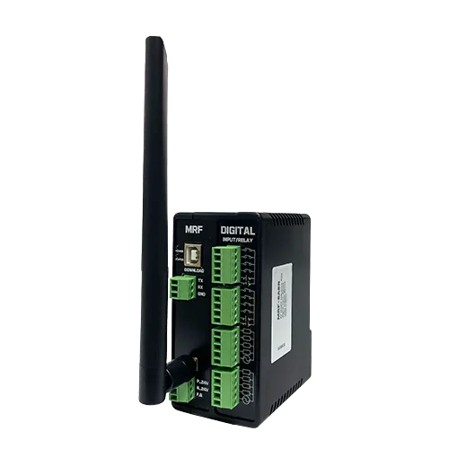
MRF-8A8R RF Remote Controller
The MRF-8A8R links the digital inputs and relay outputs of Master and Slave units over RF in both directions. It has a default one-to-one operation, with control conditions configurable on the Master.
International shipping (EMS) — calculated at checkout by destination & weight
Ships the next business day (regardless of order time)
Large orders may take 1 extra day to dispatch
Cancel before dispatch · request a return/exchange after delivery
MRF-8A8R: RF control between remote inputs and outputs
The MRF-8A8R links the digital inputs and relay outputs of Master and Slave units over RF. The official product detail describes control in both directions: a Master input can operate a Slave relay, and a Slave input can operate a Master relay.
A default one-to-one control pattern is configured at shipment. For a different sequence, output conditions can be programmed on the Master using inputs from both units.
MASTER
A Master input can operate a remote Slave relay. The Master can also define output conditions using inputs from both units.
SLAVE
A Slave input can operate a Master relay, providing control in the other direction.
The two unit images illustrate a radio-linked installation. Master and Slave are selected as individual units when ordering; they are not a two-unit bundle.
Default input-to-relay operation
The manufacturer's product detail gives these examples of the default operation.
| Input condition | Output at the other unit |
|---|---|
| Master digital input ON | Slave relay output ON |
| Slave digital input ON | Master relay output ON |
This table describes the factory one-to-one pattern. If the program is changed, the configured logic determines operation.
Define control conditions on the Master
MP STUDIO
In MP STUDIO, the Master uses inputs from both units to define output conditions on either side. Use this to change the default one-to-one pattern.
Arduino IDE
The official product detail also describes Arduino IDE programming. Request the Arduino IDE configuration by phone when ordering.
HMI connection over RS-232
The manufacturer describes RS-232 HMI connectivity for Master and Slave units. Its example connects a PC or touch display using Modbus RTU or LS Cnet.
Master and Slave unit configuration
These values summarize the configuration table in the manufacturer’s product detail.
| Item | Stated for Master and Slave |
|---|---|
| Radio | FSK / 2.4 GHz |
| Unit supply | DC 9–24 V |
| Digital inputs | 8 per unit, DC 5–24 V, NPN/PNP |
| Relay outputs | 8 per unit |
| HMI connection | RS-232, Modbus RTU or LS Cnet |
| Slave connection | Official detail states up to 32 Slaves per Master |
843 m radio communication test
843 m
The official ILOGICS product detail reports a successful communication test between two locations 843 m apart.
Test settings: Air rate 9600 bps, 20 dBm.
Communication distance may vary with local installation conditions.
Add the I/O modules your application needs
Choose Master or Slave first, then select any additional digital, X, Y, F, or K modules.
| Option group | Choices shown on the official order page |
|---|---|
| Digital module | 8A8T, 8A8R, 16A, 16R |
| X | Analog input module |
| Y | Analog output module |
| F | PT100 Ω temperature input module |
| K | Pulse output module |
Master/Slave is required; the additional module groups are optional. Check the quantity of each Master and Slave unit before ordering.
I/O contact names in MP STUDIO
These are example contact names used in the program to address I/O. Check them separately from physical wiring terminal numbers.
| Unit | Digital input contacts | Relay output contacts |
|---|---|---|
| Master | P0– P7 | P32– P39 |
| First Slave | #P1.0– #P1.7 | #P1.32– #P1.39 |
| Next Slave example | #P2.0– #P2.7 | #P2.32– #P2.39 |
Select Master or Slave for each unit and confirm the required quantity and add-on modules before ordering.