
Table of Contents
MPA-16A16T
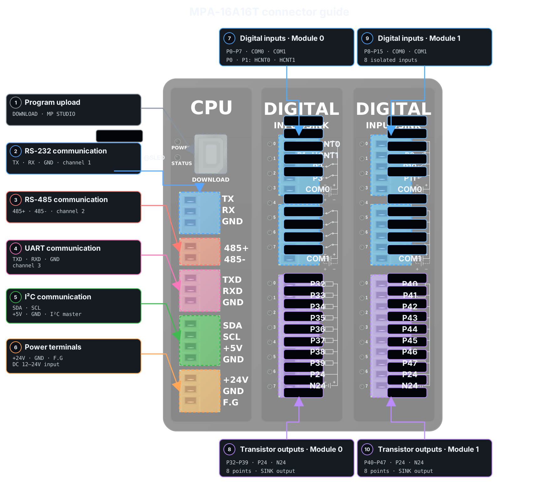
MPA Series is an assembled industrial PLC combining a CPU module with digital input and output modules.
Analog input/output, temperature sensor input, and high-speed pulse output modules can be added as options.
The selected I/O and optional modules are assembled and shipped as one product. Users cannot add or remove modules.
MPA-16A16T provides 16 digital inputs and 16 SINK transistor outputs.
Program with ladder logic using MP STUDIO.
Product Specifications
| Category | Quantity | Terminal / Item | Specifications |
|---|---|---|---|
| Programming method | - | - | MP STUDIO MP STUDIO2 (Ladder logic program) |
| Power | - | Supply voltage | DC 12~24V For DC 24V, a power supply rated 0.5A or more is recommended |
| Digital inputs | 16 points (Isolated) | Module 0: P0~P7 Module 1: P8~P15 | Operating input voltage DC 0~80V HIGH detection: DC 5V or higher Optocoupler isolation |
| Transistor outputs | 16 points (Isolated SINK) | Module 0: P32~P39 Module 1: P40~P47 | P24: DC 5~24V Load voltage DC 0~100V Max. 1A/1 points, 8A/1COM |
| High-speed counter inputs | 2 points (Isolated) | P0, P1 | Max. 8kHz Shared with digital inputs |
| Encoder Inputs | 2 points (Isolated) | P0(A)·P2(B) P1(A)·P3(B) | Max. 8kHz Shared with high-speed counter inputs |
| Optional modules | up to 20 points | Analog inputs PT100Ω temperature sensor input | Optional specifications |
| up to 12 points | Analog outputs High-speed pulse outputs | Optional specifications | |
| Communication Channels | 1 channel each | RS-232 RS-485 UART I²C | Built into the CPU module |
| Memory | - | Flash Data | 256KB 8KB |
Digital inputs
See the one-channel digital-input check before wiring for the first time. →
| Module | Group | Input contacts | Input configuration | Terminal blocks and wiring examples |
|---|---|---|---|---|
| Module 0 | COM0 COM1 | P0~P3 P4~P7 | 8 isolated digital inputs 4 points/1COM P0/P1 share high-speed counter inputs |  |
| Module 1 | COM0 COM1 | P8~P11 P12~P15 | 8 isolated digital inputs 4 points/1COM |
The diagram shows a wiring example for module 0. For other modules, use the corresponding contact numbers in the table. This example uses a DC 24V supply; each group can use PNP or NPN depending on its COM wiring.
The digital inputs are isolated by optocouplers. NPN or PNP switches and sensors can be used depending on the COM terminal wiring of each input module.
Transistor outputs
See the one-channel SINK transistor-output check before wiring for the first time. →
| Module | Output contacts | Output power | Output configuration | Terminal blocks and wiring examples |
|---|---|---|---|---|
| Module 0 | P32~P39 | P24 N24 | 8 isolated SINK transistor outputs |  |
| Module 1 | P40~P47 | P24 N24 | 8 isolated SINK transistor outputs |
The diagram shows a wiring example for module 0. For other modules, use the corresponding contact numbers in the table.
Connect DC 5~24V to P24 on each module and connect the supply GND to N24. When the output is ON, the output contact is connected to the GND supplied at N24.
High-speed counter / Encoder inputs
| Function | Contact | Maximum input frequency | Shared functions | Input signal connection |
|---|---|---|---|---|
| High-speed counters 0·1 | P0, P1 | 8kHz | Digital inputs |  |
| Encoder 0 | P0(A), P2(B) | 8kHz | High-speed counter 0 |  |
| Encoder 1 | P1(A), P3(B) | 8kHz | High-speed counter 1 |  |
The diagram shows the input contacts for the high-speed counter pulse signal and encoder phases A and B. Power and common wiring for the isolated inputs are not included in this diagram.
Optional modules
| Module | Maximum points | Function |
|---|---|---|
| Analog inputs | 20 points | DC 0~5V, DC 0~10V, 0~20mA or NTC temperature sensor input |
| PT100Ω temperature sensor input | 20 points | 2-wire or 3-wire PT100Ω temperature sensor input |
| Analog outputs | 12 points | DC 0~5V, DC 0~10V or 0~20mA output |
| High-speed pulse outputs | 12 points | Pulse output up to 1MHz |
Communication and program upload
| Function | channel | Terminals / Ports | Usage | Device wiring |
|---|---|---|---|---|
| Program upload and monitoring | - | DOWNLOAD | Select as download port in MP STUDIO |  |
| RS-232 | Channel 1 | TX, RX, GND | Use MP STUDIO communication port settings | |
| RS-485 | Channel 2 | 485+, 485- | Use MP STUDIO communication port settings | |
| UART | channel 3 | TXD, RXD, GND | Use MP STUDIO communication port settings | |
| I²C | 1 channel | SDA, SCL | Master communication |
The I²C diagram shows a connection example for a 5V device. Check the other device's signal voltage before connecting UART.
Status LED
Control the CPU module STATUS LED with the @SLED contact in MP STUDIO.
Development environment setup
- Connect the computer to the CPU module DOWNLOAD port with a USB cable.
- Check the download port's COM number in Device Manager.
- In MP STUDIO, open the
MPAtab and selectMPA-16A16R(T). - Set the verified COM number as the download port, then download the ladder program.
Dimensions
| Item | Dimensions |
|---|---|
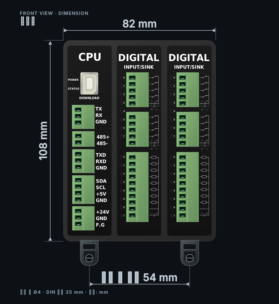
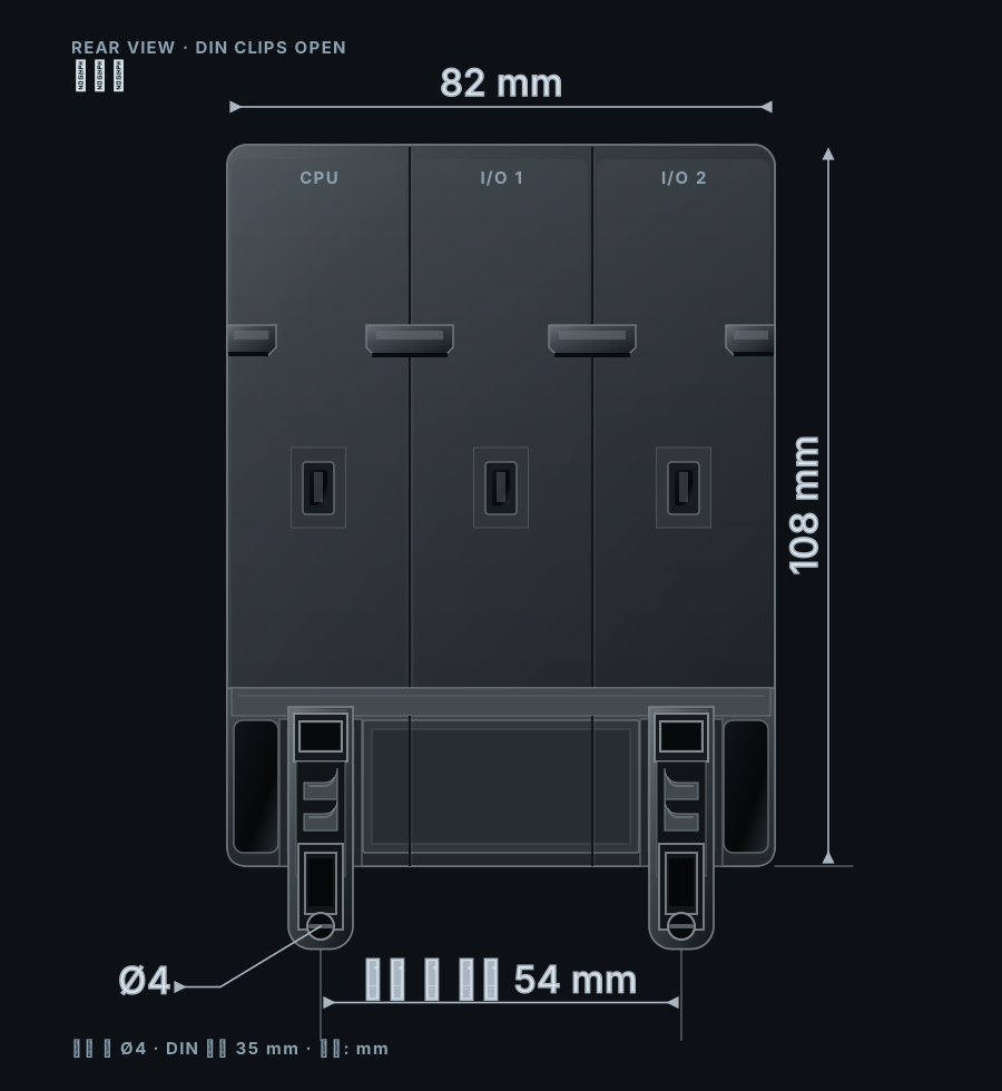
| Product width | 82mm |
| Body height | 108mm |
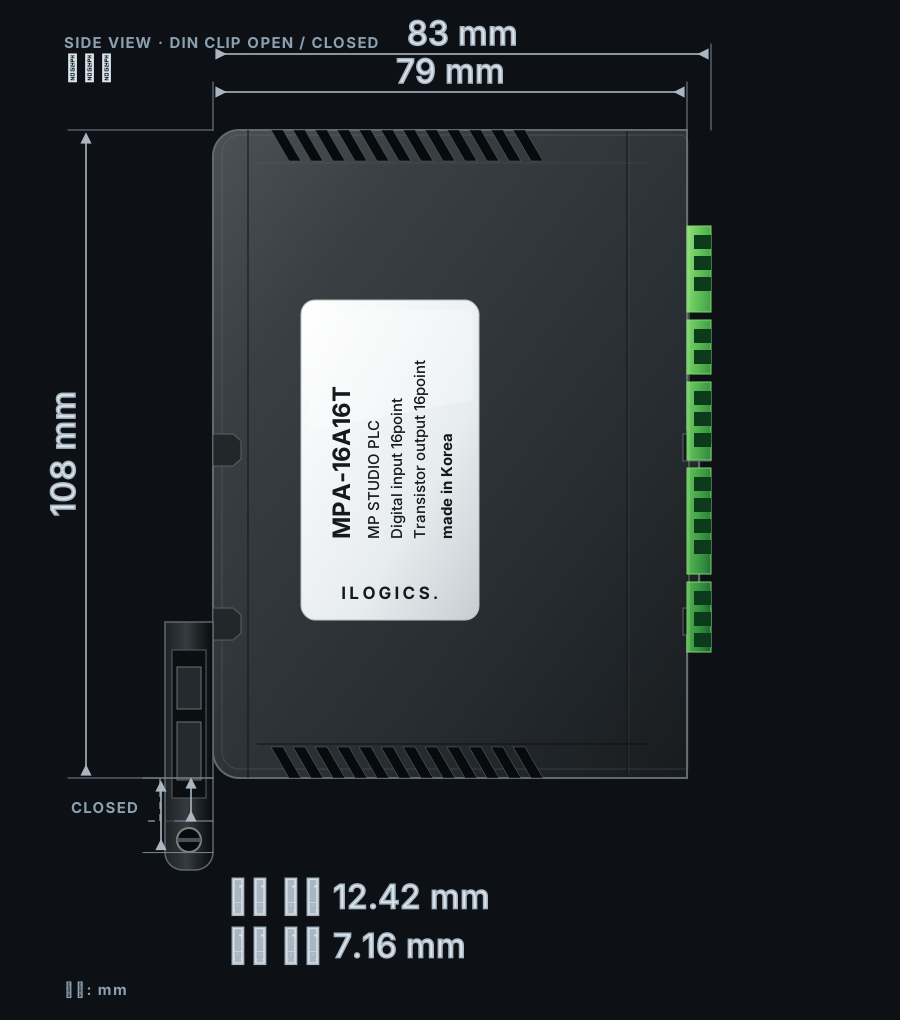
| Overall height | Clip open: 120.42mm Clip closed: 115.16mm |
| Product depth | Body: 79mm Maximum with terminals: 83mm |
| Mounting hole spacing | 54mm |
| Mounting hole diameter | Ø4mm |
| DIN rail | 35mm |
| Front view | Side view |
|---|---|
 |  |
| Rear view | |
 |