
Table of Contents
MNET-8A8R
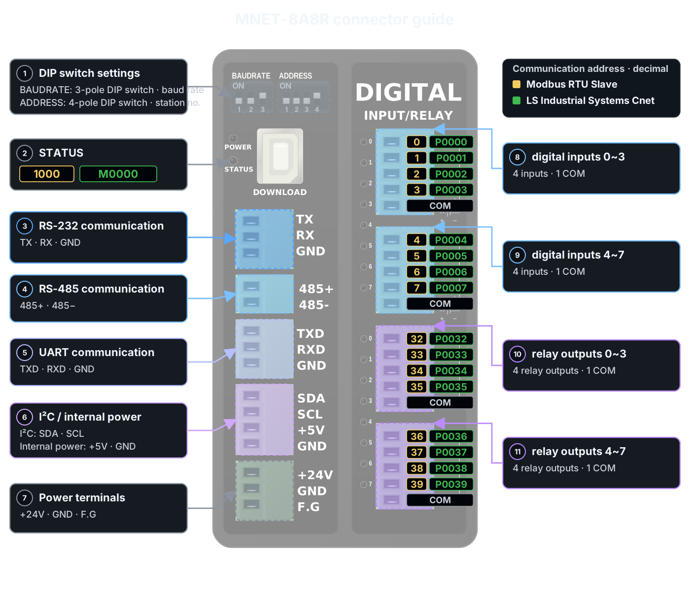
MNET-8A8R is a communication slave product whose digital I/O, analog I/O, temperature sensor inputs, and high-speed pulse I/O can be controlled from a master device such as a PC, HMI, or PLC using Modbus or LS Industrial Systems Cnet.
Consists of a CPU module (1 RS-232 channel, 1 RS-485 channel, and 1 UART channel) and an I/O module (8 digital inputs and 8 relay outputs).
Select Modbus RTU Slave or LS Industrial Systems Cnet Slave in the options when ordering.
Product Specifications
| Category | Quantity | Terminals / Addresses | Specifications |
|---|---|---|---|
| Product role | - | - | Communication slave I/O No user program |
| Power | - | +24V, GND, F.G | DC 12~24V For DC 24V, a power supply rated 0.5A or more is recommended |
| Digital inputs | 8 points (Isolated) | 0~7 Modbus 0~7 Cnet P0000~P0007 | Operating input voltage DC 0~80V HIGH detection: DC 5V or higher Optocoupler isolation |
| Relay outputs | 8 points (Isolated dry contacts) | 0~7 Modbus 32~39 Cnet P0032~P0039 | DC 0~30V or AC 0~250V Max. 5A/1 points, 8A/1COM |
| Communication protocol | Order option | Modbus RTU Slave LS Industrial Systems Cnet Slave | Select one of the two protocols when ordering |
| Communication Channels | 1 channel each | RS-232 RS-485 UART | Use the port wired to the master device |
| I²C | 1 channel | SDA, SCL | CPU module terminals |
| Internal power | - | +5V, GND | Int VCC terminals |
| Mounting | - | - | 35mm DIN rail |
Communication terminals
Check the CPU module communication terminals and internal power terminals.
| Communication interface | Product terminal labels | Device connection example |
|---|---|---|
| RS-232 | TX, RX, GND |  |
| RS-485 | 485+, 485− | |
| UART | TXD, RXD, GND | |
| I²C / internal power | SDA, SCL / +5V, GND |
Cross the transmit and receive terminals for RS-232 and UART; match polarities for RS-485. For UART, verify that the signal voltage is compatible with the other device.
Digital inputs
See the one-channel digital-input check before wiring for the first time. →
| Input group | Communication address | Input configuration | Terminal blocks and wiring examples |
|---|---|---|---|
| 0~3 | Modbus 0~3 Cnet P0000~P0003 | 4 isolated inputs 4 points / 1COM |  |
| 4~7 | Modbus 4~7 Cnet P0004~P0007 | 4 isolated inputs 4 points / 1COM |
Each group of 4 inputs shares one COM terminal, and both groups support PNP or NPN wiring. For PNP, connect COM to supply −; for NPN, connect COM to supply +.
The DC 24V shown in the diagram is a wiring example. The operating input voltage is DC 0~80V, and HIGH detection requires DC 5V or higher.
Relay outputs
See the one-channel relay-output check before wiring for the first time. →
| Output group | Communication address | Output configuration | Terminal blocks and wiring examples |
|---|---|---|---|
| 0~3 | Modbus 32~35 Cnet P0032~P0035 | 4 dry contacts 4 points / 1COM |  |
| 4~7 | Modbus 36~39 Cnet P0036~P0039 | 4 dry contacts 4 points / 1COM |
Relay outputs share one COM terminal for every 4 points. The output contact rating is DC 0~30V or AC 0~250V, with a maximum allowable current of 5A/1 point and 8A/1COM.
Basic I/O communication addresses
| Category | Points | Modbus RTU internal address (Decimal) | LS Industrial Systems Cnet | Operation |
|---|---|---|---|---|
| Input | 0~7 | 0~7 | P0000~P0007 | Read |
| Output | 0~7 | 32~39 | P0032~P0039 | Read / Write |
| State | - | 1000 | M0000 | Check status |
DIP switch settings
The baud-rate DIP switch has 3 bits; switches 1·2·3 have values 4·2·1 respectively. The leftmost switch is the most significant bit.
| Set value | Baud rate | Switch 1 | Switch 2 | Switch 3 | Switch appearance |
|---|---|---|---|---|---|
| 0 | 9,600bps | OFF | OFF | OFF | 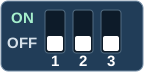 |
| 1 | 14,400bps | OFF | OFF | ON | 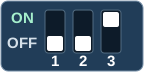 |
| 2 | 19,200bps | OFF | ON | OFF | 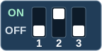 |
| 3 | 28,800bps | OFF | ON | ON | 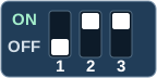 |
| 4 | 38,400bps | ON | OFF | OFF | 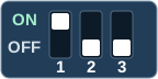 |
| 5 | 57,600bps | ON | OFF | ON | 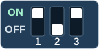 |
| 6 | 76,800bps | ON | ON | OFF | 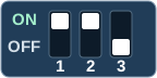 |
| 7 | 115,200bps | ON | ON | ON | 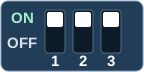 |
The slave-address DIP switch has 4 bits; switches 1·2·3·4 have values 8·4·2·1 respectively. Form the desired address by adding the values of the selected switches.
| Setting example | Switch 1 (8) | Switch 2 (4) | Switch 3 (2) | Switch 4 (1) | Switch appearance |
|---|---|---|---|---|---|
| Address 0 | OFF | OFF | OFF | OFF | 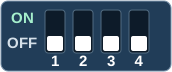 |
| Address 1 | OFF | OFF | OFF | ON | 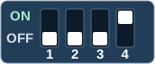 |
| Address 5 | OFF | ON | OFF | ON | 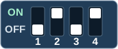 |
| Address 10 | ON | OFF | ON | OFF | 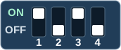 |
| Address 15 | ON | ON | ON | ON | 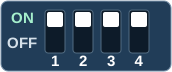 |
Set the DIP switches with power off. The master device's baud rate, data bits, parity, and stop bits must match the communication settings of the delivered product.
Optional modules
| Code | Function | Points per module | Maximum configuration | Value format |
|---|---|---|---|---|
| X | Analog inputs | 4 points | X~X5, up to 20 points | 15bit, 0~32,767 NTC mode: temperature ×10 |
| F | PT100Ω temperature sensor input | 4 points | F~F5, up to 20 points | −200~800℃ Temperature ×10 |
| Y | Analog outputs | 3 points | Y~Y4, up to 12 points | 16bit, 0~65,535 |
| K | High-speed pulse outputs | 6 points | K~K2, up to 12 points | DC 5V, 30mA or less Max. 1MHz |
The X module offers selectable DC 0~5V, DC 0~10V, 0(4)~20mA, or NTC inputs. Connect a 2-wire or 3-wire PT100Ω sensor to the F module. The Y module offers selectable DC 0~5V, DC 0~10V, or 0(4)~20mA outputs.
Available option combinations depend on the product. Products with optional modules are assembled in the selected configuration, so exchanges or refunds after purchase may be difficult.
Configure analog inputs (X) and PT100Ω inputs (F) for a combined maximum of 20 points, and analog outputs (Y) and high-speed pulse outputs (K) for a combined maximum of 12 points. You cannot order a configuration that simply adds the maximum point count of every module.
Options are assembled and shipped in the selected configuration; users cannot add or remove I/O or optional modules. Also see MNET Series option configuration guide.
Interpreting option values
- X analog input values range from 0~32,767. Interpret them according to the selected input mode.
- X in NTC mode and F PT100Ω inputs transmit temperature multiplied by 10. For example, a received value of 213 means 21.3℃.
- Y output settings range from 0~65,535. Use them according to the selected output mode.
- K has a fixed WIDTH of 65,535 and outputs pulses from a Duty setting of 0~65,535. Contact us when ordering if you need to change the frequency or output pulse count.
Option module communication addresses
Use the address ranges below that correspond to the installed optional modules. The slave-address DIP switch selects the station address of the product to communicate with; the addresses in this table select items to read or write within that product.
| Module | channel | Modbus RTU internal address (Decimal) | LS Industrial Systems Cnet |
|---|---|---|---|
| X1 | 0~3 | 2000~2003 | D0000~D0003 |
| X2 | 4~7 | 2004~2007 | D0004~D0007 |
| X3 | - | 2008~2011 | D0008~D0011 |
| X4 | - | 2012~2015 | D0012~D0015 |
| X5 | - | 2016~2019 | D0016~D0019 |
| Y1 | 0~2 | 2020~2022 | D0020~D0022 |
| Y2 | 3~5 | 2023~2025 | D0023~D0025 |
| Y3 | 6~8 | 2026~2028 | D0026~D0028 |
| Y4 | 9~11 | 2029~2031 | D0029~D0031 |
| F1 | 0~3 | 2040~2043 | D0040~D0043 |
| F2 | 4~7 | 2044~2047 | D0044~D0047 |
| F3 | - | 2048~2051 | D0048~D0051 |
| F4 | - | 2052~2055 | D0052~D0055 |
| F5 | - | 2056~2059 | D0056~D0059 |
| K1 | PWM0~PWM5 | 2060~2065 | D0060~D0065 |
| K2 | PWM6~PWM11 | 2066~2071 | D0066~D0071 |
The confirmed separate addresses for the X module in NTC mode are as follows.
| Module | Modbus RTU internal address (Decimal) | LS Industrial Systems Cnet |
|---|---|---|
| X1 NTC | 2080~2083 | D2080~D2083 |
| X2 NTC | 2084~2087 | D2084~D2087 |
The Cnet addresses for NTC are D2080~D2087. Enter these addresses using their own notation, distinguishing it from other option addresses.
Communication startup sequence
- Verify that the ordered product's communication protocol matches the master device.
- Turn off power and wire the required RS-232, RS-485, or UART port.
- Set the baud-rate and slave-address DIP switches.
- Match the master device port, baud rate, data bits, parity, stop bits, and target slave address to the delivered product settings.
- Check wiring and settings, then turn on the power.
- Read the first input to check communication. The Modbus RTU internal address is
0and the LS Industrial Systems Cnet address isP0000. - Verify that the load is safe for an output test, then control the first output. The Modbus RTU internal address is
32and the LS Industrial Systems Cnet address isP0032. - After verification, apply all required addresses in order.