
Table of Contents
MPAINO X analog input module
When ordering an MPAINO Series product, you can add an analog input X module to the I/O module configuration.
Use each channel's DIP switches to select DC 0~5V, DC 0~10V, DC 0(4)~20mA, or NTC thermistor temperature sensor input.
The combined channel count of analog input and PT100Ω temperature sensor input modules cannot exceed 20.
For DC 0~5V, DC 0~10V, and DC 0~20mA, use analogRead(), analogReadAvg(), and IanalogRead().
For DC 4~20mA, use analogRead2(), analogRead2Avg(), and IanalogRead2().
Product Specifications

| Item | Details |
|---|---|
| Product category | MPAINO optional analog input module |
| Option code | X, X2, X3, X4, X5 |
| Inputs per module | 4 channels — CH0, CH1, CH2, CH3 |
| Input type | DC 0~5V / 1~5V / 0~10V / 0~20mA / 4~20mA / NTC temperature sensor |
| Mode selection | Per-channel DIP switch settings |
| A/D converter IC | ADS1118 |
| Effective resolution | 15bit — raw values 0~32767 over the rated voltage/current input range |
| NTC sensor specification | 10kΩ at 25°C, B value (β) 3950K |
| NTC return units | ntcRead(): integer temperature × 10 / ntcReadf(): floating-point °C |
| NTC display resolution | 0.1°C — this is not a guaranteed measurement accuracy. |
| Configuration limit | Up to 5 X modules, 20 points total. Combined X and F configurations also allow a maximum of 20 input points. |
| Operating environment | Use built-in commands in the ILOGICS board package for MPAINO |
Resolution and accuracy are different. 15bit indicates the number of distinct value steps. Actual measurement error is affected by the sensor, signal source, wiring, noise, and other factors. The formulas on this page describe calculations over the rated range; they do not represent calibration results or isolation/overvoltage protection ratings.
Order configuration and module count
| Option | Number of X modules | Number of analog inputs | Numbers used in the program ※ |
|---|---|---|---|
| X | 1 units | 4 points | 0~3 |
| X2 | 2 units | 8 points | 0~7 |
| X3 | 3 units | 12 points | 0~11 |
| X4 | 4 units | 16 points | 0~15 |
| X5 | 5 units | 20 points | 0~19 |
※ The channel numbers in the table assume the analog input options consist only of X modules. For products also containing F (PT100 input) modules, check the module order and channel table for the factory configuration.
- Confirm the signal types and number of inputs needed when ordering. 4 channels means 4 separate inputs, not reading one measurement four times.
- X is an input module. Voltage/current output requires a Y module; reading PT100 sensors requires an F module.
- The selected modules are assembled before shipment; users do not add or remove modules themselves.
- When combining options, verify that the ordered product supports the desired configuration.
Input modes and DIP switches
The diagram below shows CH0~CH3 configured identically for each of the four input modes. Left is ON and right is OFF; yellow indicates the ON position. In practice, set only the DIP switches of the channels you will use to the corresponding input mode.
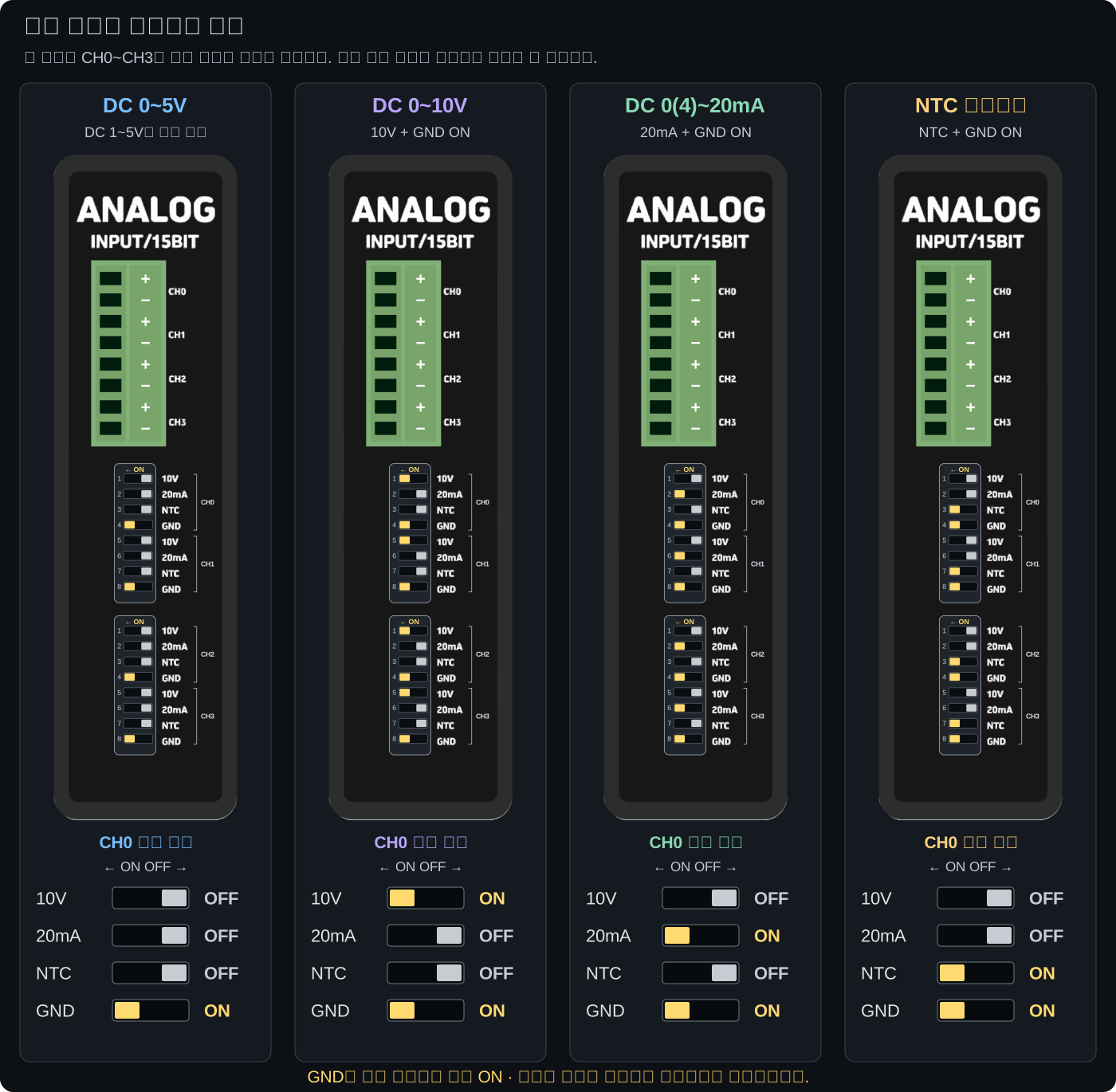
Set each channel to match the sensor output
Each channel has 10V, 20mA, NTC, and GND settings. Select the combination for the input mode and always keep the GND switch ON. GND is ON at shipment.
| Signal to connect | 10V | 20mA | NTC | GND | Interpreting the reading |
|---|---|---|---|---|---|
| DC 0~5V | OFF | OFF | OFF | ON | Raw value 0~32767 → 0~5V |
| DC 1~5V | OFF | OFF | OFF | ON | Read in 0~5V mode and handle the 1V offset in the program |
| DC 0~10V | ON | OFF | OFF | ON | Raw value 0~32767 → 0~10V |
| DC 0~20mA | OFF | ON | OFF | ON | Raw value 0~32767 → 0~20mA |
| DC 4~20mA | OFF | ON | OFF | ON | analogRead2() can handle the 4mA offset |
| NTC 10kΩ / β3950 | OFF | OFF | ON | ON | Read temperature with ntcRead() or ntcReadf() |
Configuration precautions
- Work with the product and connected devices powered off and input signals removed.
- First verify that you are using the correct channel's switch group. Changing CH1 switches does not change CH0 settings.
- Use the ON direction marked on the switch body as the reference. Do not rely only on left/right orientation in a photo.
- Do not arbitrarily turn
10V,20mA, andNTCON together. Use the combinations in the table above. - Recheck wiring and settings before applying power.
The program does not automatically detect the DIP switch positions. analogReadInit() also does not change the input mode. The hardware settings must match the program's conversion range.
Can each channel use a different input mode?
Each channel has its own mode switches, allowing configurations such as CH0 for 0~10V, CH1 for 4~20mA, and CH2 for NTC. In the program, also use the read function and conversion formula appropriate to each channel. Do not apply voltage or current signals to an NTC channel.
Wiring by signal type
Check input terminals
| Channel marked on the module | Input terminals | Program number for the first X module |
|---|---|---|
| CH0 | CH0 + / CH0 − | 0 |
| CH1 | CH1 + / CH1 − | 1 |
| CH2 | CH2 + / CH2 − | 2 |
| CH3 | CH3 + / CH3 − | 3 |
Use + and − of the same channel as a pair. The diagram below is a conceptual illustration of connections, not a drawing of the product outline or actual terminal positions and spacing. First verify the channel names and polarity on the actual product.

DC 0~5V / 1~5V / 0~10V
- Connect the sensor's analog voltage output + to
+of the channel used. - Connect the sensor's signal return (−) to
−of the same channel. - Connect sensor power separately according to the manufacturer's wiring diagram. Do not confuse sensor power + with signal output +.
- Select the voltage range from the DIP settings table. A 1~5V sensor uses the same switch settings as 0~5V.
For a flowmeter with a 0~30000 L/min range and 0~10V output, configure CH0 for 0~10V and scale the raw value 0~32767 to 0~30000 L/min. The runnable example below uses the same conditions.
DC 0~20mA / 4~20mA
Set 20mA and GND ON for the channel. Wire current signals according to the sensor manufacturer's diagram so that current flows through +/− of the same channel.
2-wire loop-powered sensors and 3-/4-wire sensors use different wiring. First check the sensor power scheme, current-output polarity, and output return. Without knowing the signal-source specifications, do not copy the voltage-input wiring example or apply supply voltage directly across channel +/−. If no wiring diagram is available, check the sensor model and documentation before connecting it.
0~20mA and 4~20mA use the same hardware switch settings. The difference is whether the program treats 4mA as the start of the measurement range. analogRead2() does not supply current to the sensor or change the DIP settings.
NTC temperature sensor
- Verify the NTC 10kΩ(25°C), β3950 specification. The same resistance with a different B value will give an incorrect temperature conversion.
- Connect the two wires of an unpowered passive NTC sensor to +/− of the same channel.
- Set
NTCandGNDON for the channel. - Read °C with
ntcReadf(ch), or an integer temperature × 10 withntcRead(ch).
PT100 sensors, thermocouples, and voltage-output temperature transmitters are not covered by this NTC setting. Read voltage/current-output temperature transmitters in the matching voltage/current mode, then scale the result to the sensor's temperature range.
Module labels and program channel numbers
The front of each X module repeats the labels CH0~CH3. In the program, channel numbering continues across modules.
| X module order ※ | Front CH0 | Front CH1 | Front CH2 | Front CH3 |
|---|---|---|---|---|
| First | 0 | 1 | 2 | 3 |
| Second | 4 | 5 | 6 | 7 |
| Third | 8 | 9 | 10 | 11 |
| Fourth | 12 | 13 | 14 | 15 |
| Fifth | 16 | 17 | 18 | 19 |
※ This logical channel table applies to configurations containing only X modules. Check the module order against the factory configuration.
For example, use analogRead(5) to read CH1 on the second X module of an X2 product. MPAINO uses module logical numbers; do not replace 0 on this page with Arduino A0. Digital input 0 and analog input 0 are also numbers for different functions.
A maximum number of 19 does not mean every product has 20 installed channels. Read only the channels actually installed. Do not use values returned for invalid numbers or uninstalled channels as valid sensor readings.
First measurement sequence
- Check the sensor: Verify the signal type and range (voltage, current, or NTC), sensor power, and wiring diagram.
- Choose a channel: Start with only CH0 on the first X module.
- Configure with power off: Set CH0 according to the DIP table above, check the polarity, and wire it.
- Select the development environment: In Arduino IDE, select the ILOGICS board and download port matching the actual MPAINO model. If the board package has an
Analog Input Modulemenu, selectX / X2 / X3 / X4 / X5to match the factory configuration. Match all other options to the actual configuration as well. - Check the raw value: Upload example 1 below and open the Serial Monitor at 115200 baud.
- Check input changes: Apply a known signal within the rated range and verify that the value changes in the expected direction.
- Convert to engineering units: After verifying voltage/current measurements, scale them to the sensor's measurement range, such as flow or pressure.
- Add channels: Once one channel is working correctly, add the remaining channels one at a time.
Each example below is an independent Arduino sketch. Use only one example at a time. These examples use the current MPAINO built-in functions; there is no need to include a separate ILIB.h or create an IADC object directly. If a function-not-declared error occurs, check the selected board and installed ILOGICS board package.
Example 1 · Check raw values first
Read the voltage or current signal connected to CH0 of the first X module. First set the input mode with the DIP switches.
const uint8_t inputChannel = 0;

void setup() {
  Serial.begin(115200);
  analogReadInit(IANALOG_SPS_64);
}

void loop() {
  const int raw = analogRead(inputChannel);
  Serial.print(F("CH0 raw = "));
  Serial.println(raw);
  delay(200);
}
| Configured input range | Start input | Midpoint input | End input |
|---|---|---|---|
| 0~5V | 0V → approx. 0 | 2.5V → approx. 16384 | 5V → approx. 32767 |
| 0~10V | 0V → approx. 0 | 5V → approx. 16384 | 10V → approx. 32767 |
| 0~20mA | 0mA → approx. 0 | 10mA → approx. 16384 | 20mA → approx. 32767 |
| Reading 4~20mA as raw values | 4mA → approx. 6553 | 12mA → approx. 19660 | 20mA → approx. 32767 |
The table is an ideal conversion reference, not a pass/fail tolerance table. A nonzero raw value at 4mA is normal. To map 4mA to 0, see example 3. For NTC, use the dedicated temperature functions instead of this linear conversion table.
Example 2 · Read a 0~10V flow meter
Conditions: CH0 of the first X module, 10V=ON / 20mA=OFF / NTC=OFF / GND=ON, sensor output 0~10V, measurement range 0~30000 L/min. For a different sensor, set fullScaleFlow to its actual range.
const uint8_t inputChannel = 0;
const float fullScaleFlow = 30000.0F;

void setup() {
  Serial.begin(115200);
  analogReadInit(IANALOG_SPS_64);
}

void loop() {
  const int raw = analogRead(inputChannel);
  const float voltage = raw * (10.0F / 32767.0F);
  const float flow = raw * (fullScaleFlow / 32767.0F);

  Serial.print(F("Voltage = "));
  Serial.print(voltage, 3);
  Serial.print(F(" V, Flow = "));
  Serial.print(flow, 1);
  Serial.println(F(" L/min"));
  delay(200);
}
At a 5V input, the calculated value is approximately 15000 L/min. Displaying more decimal places does not improve sensor or module accuracy.
Conversion formulas for other signal ranges
| Purpose | Calculation using raw value raw |
|---|---|
| 0~5V voltage | raw * (5.0F / 32767.0F) |
| 0~10V voltage | raw * (10.0F / 32767.0F) |
| 0~20mA current | raw * (20.0F / 32767.0F) |
| Sensor measurement starting at 0 | raw * (sensorMaximum / 32767.0F) |
| Range ratio of a 1~5V sensor | First voltage = raw * (5.0F / 32767.0F), then ratio = (voltage - 1.0F) / 4.0F |
Convert a 1~5V sensor to engineering units with minimum + ratio * (maximum - minimum). If ratio is below 0 or above 1, it is out of range; handle it separately according to the sensor specifications. Unconditionally clipping the display to 0~1 may hide abnormal conditions. analogRead2() is for 4~20mA; do not use it for 1~5V signals.
Use floating-point constants as shown in the example to avoid 16bit integer overflow during calculations. For example, avoid calculating raw * 30000 as an integer before dividing.
Example 3 · 4~20mA pressure gauge and error handling
Conditions: CH0 of the first X module, 10V=OFF / 20mA=ON / NTC=OFF / GND=ON, sensor output 4~20mA, measurement range 0~10bar. If the sensor's actual pressure range differs, change fullScalePressure.
analogRead2() handles the 4mA offset and scales the measurement range to 0~32767. Receive the result in uint16_t so it can store the error value 65535. Do not use the ordinary AVR int type.
const uint8_t inputChannel = 0;
const float fullScalePressure = 10.0F;

void setup() {
  Serial.begin(115200);
  analogReadInit(IANALOG_SPS_64);
}

void loop() {
  const uint16_t value = analogRead2(inputChannel);

  if (value == ANALOG_READ2_ERROR) {
    Serial.println(F("INPUT ERROR: check sensor, supply and wiring"));
    // Do not use the reading as a valid control value in this branch.
  } else {
    const float pressure = value * (fullScalePressure / 32767.0F);
    Serial.print(F("Pressure = "));
    Serial.print(pressure, 2);
    Serial.println(F(" bar"));
  }
  delay(200);
}
When is it an error?
The current MPAINO built-in functions use the following criteria. These are software evaluation criteria and do not replace the sensor's diagnostic specifications.
| Raw value from analogRead | analogRead2 result | Meaning |
|---|---|---|
| Below 5898 | ANALOG_READ2_ERROR = 65535 | Low-input error corresponding to below approximately 3.6mA |
| 5898~6554 | 0 | Treat the allowed region around and below 4mA as the start value |
| Above 6554 up to 32767 | Scale to 0~32767 | Proportion within the 4~20mA measurement range |
An input slightly below 4mA therefore does not always produce an error. On an error, check not only for an open circuit but also sensor power, polarity, mode settings, and channel number. A return value within the normal range alone does not guarantee correct wiring or absence of overcurrent. Safety control requires separate diagnostics and safety measures appropriate to the equipment.
The averaging function analogRead2Avg() returns −1 for errors; receive it in int32_t and compare it with ANALOG_READ2_AVG_ERROR. Do not confuse this with the normal read error value 65535.
Example 4 · Read NTC temperature
Conditions: an NTC 10kΩ (25°C), β3950 sensor connected to CH0 of the first X module, 10V=OFF / 20mA=OFF / NTC=ON / GND=ON.
const uint8_t temperatureChannel = 0;

void setup() {
  Serial.begin(115200);
  analogReadInit(IANALOG_SPS_64);
}

void loop() {
  const float temperature = ntcReadf(temperatureChannel);
  Serial.print(F("Temperature = "));
  Serial.print(temperature, 1);
  Serial.println(F(" C"));
  delay(500);
}
To work with an integer, use int temperature10 = ntcRead(0);. A return value of 253 means 25.3°C, and -55 means −5.5°C. ntcReadf() converts the same result to floating-point °C; it does not provide higher measurement resolution.
The current temperature conversion table limits values to −40.0~120.0°C. This is not a guaranteed operating temperature range for the connected sensor or the finished product. No dedicated open-/short-circuit error code is returned. If an endpoint value repeats, check the sensor and wiring rather than assuming it is the actual temperature. A return value of 0 for an invalid channel number is also indistinguishable from a valid 0°C, so specify the actually installed channel correctly.
Reading fluctuations and measurement speed
Stabilize the display with a moving average
analogReadAvg(0, 8) reads one new value from CH0 and averages up to 8 recent readings. One call does not perform 8 consecutive measurements. Repeated calls build the averaging history; initially, only the readings actually collected are averaged.
void setup() {
  Serial.begin(115200);
  analogReadInit(IANALOG_SPS_64);
}

void loop() {
  const int32_t average = analogReadAvg(0, 8);
  Serial.println(average);
  delay(100);
}
The maximum averaging count is 20. 0 returns a fresh, unaveraged value; values above 20 are limited to 20. More averaging may smooth the display, but also slows the response to changes. The example calls the function at intervals of approximately 100ms or more, so a full history of 8 values includes measurements spanning about 0.8 seconds. First check the wiring and signal source, then apply only as much averaging as needed.
For 4~20mA, use analogRead2Avg() and check for error −1 first. An averaging filter does not correct faulty wiring; if memory allocation fails, a new raw value may be returned instead.
analogReadInit sets the sampling speed
| Setting constant | Requested target reading rate in SPS |
|---|---|
IANALOG_SPS_8 / IANALOG_SPS_16 / IANALOG_SPS_32 | 8 / 16 / 32 |
IANALOG_SPS_64 | 64 — baseline for the introductory example |
IANALOG_SPS_128 / IANALOG_SPS_250 / IANALOG_SPS_475 | 128 / 250 / 475 |
If analogReadInit() is omitted, the default target is 64 SPS. The setting applies to all MPAINO analog input modules. SPS means samples per second; it does not mean all channels update simultaneously at that rate.
Internally, each read performs two conversions to prevent a value from the previous channel from being mixed in. Actual speed is affected by conversion waits, SPI communication, channel count, serial output, delay(), and other factors. In particular, the 475 setting does not guarantee 475 actual reads per second. Two conversions are performed at an internal maximum of 860 SPS, so even conversion time alone limits the rate to approximately 430 reads/second or less; other processing adds more time.
The total update time for sequentially reading multiple channels is the sum of the individual read times. Before using a faster setting, check the required response time and value fluctuations under actual input conditions.
Checks by symptom
| Symptom | Check first |
|---|---|
| Value is 0 or very small | Check sensor power, signal presence, +/− polarity, same-channel pairing, DIP mode and whether the channel is installed |
| Value is stuck near maximum | Check that sensor output range matches the 5V/10V setting. Do not assume a saturated value is a valid full-scale reading |
| Raw value is about 6553 at 4mA | Normal raw value on a 0~20mA basis. Use analogRead2() if 4mA offset handling is needed |
| 4~20mA measurement returns 65535 | Check for a low-input error. Handle the error branch before pressure/flow conversion |
| Averaging command returns −1 | Check whether this is the analogRead2Avg() error value. Do not average it together with valid raw values |
| Second module reading differs from expected | Distinguish front labels CH0~CH3 from program numbers 4~7. Check the shipped module order |
| Reading keeps fluctuating | Check sensor power/return, terminal tightness and nearby noise sources, then adjust SPS and moving average |
| NTC temperature differs greatly | Check 10kΩ@25°C / β3950 specification, NTC and GND switches, and channel number |
| NTC is stuck near −40.0°C or 120.0°C | May be a conversion-table endpoint: check for sensor open/short circuits and wiring. Do not diagnose the fault type from the endpoint alone |
| Command compilation error | Check that the actual MPAINO board is selected and the ILOGICS board package is installed. Do not mix legacy ILIB examples and built-in commands indiscriminately |
Final checks before use
- Does the sensor output range match the channel DIP settings?
- Is the GND switch ON, and are input +/− connected to the same channel?
- Have you distinguished sensor power terminals from signal input terminals?
- Does the installed module order match the program channel numbers?
- Are 4~20mA error values handled before conversion?
- Have you avoided treating NTC endpoint values as valid temperatures or definitive fault codes?
- Have you checked actual measurements and conversions using a known input within the rated range?
Do not connect signals that exceed the input range. If the signal power scheme, common potential, or isolation requirements are unclear, check the sensor documentation and equipment configuration before connecting it. The examples on this page are for checking measurements and do not implement equipment safety interlocks.
Related commands and documents
| Purpose | Details |
|---|---|
| Read raw values / Set sampling rate | analogRead · analogReadInit |
| Moving average | analogReadAvg · analogReadAvgf |
| 4~20mA reading / Averaging | analogRead2 · analogRead2Avg · analogRead2Avgf |
| 4~20mA physical-unit conversion | IanalogRead2 · IanalogRead2f |
| Read NTC temperature | ntcRead · ntcReadf |
| Product configuration / Wiring basics | MPAINO Series · Wiring guide |